Power converter and power converter for railroad vehicle

a technology of power converter and railroad vehicle, which is applied in the direction of basic electric elements, electric apparatus construction details, solid-state devices, etc., can solve the problems of large heat generation of elements and the third semiconductor switching element, switching loss, etc., and achieve the effect of reducing or preventing failures

Active Publication Date: 2019-10-22
FUJI ELECTRIC CO LTD
View PDF13 Cites 0 Cited by
  • Summary
  • Abstract
  • Description
  • Claims
  • Application Information

AI Technical Summary

Benefits of technology

[0009]The present invention has been proposed in order to solve the aforementioned problem, and an object of the present invention is to provide a power converter and a power converter for a railroad vehicle capable of significantly reducing or preventing failures caused by insufficient heat radiation.

Problems solved by technology

Here, each of the second semiconductor switching element and the third semiconductor switching element is more frequently switched than the first semiconductor switching element and the fourth semiconductor switching element, and thus the second semiconductor switching element and the third semiconductor switching element generate a relatively large amount of heat due to an increase in the switching loss.

Method used


Image

  • Power converter and power converter for railroad vehicle
  • Power converter and power converter for railroad vehicle
  • Power converter and power converter for railroad vehicle

Examples


modified examples

[0091]The embodiments disclosed this time must be considered as illustrative in all points and not restrictive. The scope of the present invention is not shown by the above description of the embodiment but by the scope of claims for patent, and all modifications (modified examples) within the meaning and scope equivalent to the scope of claims for patent are further included.

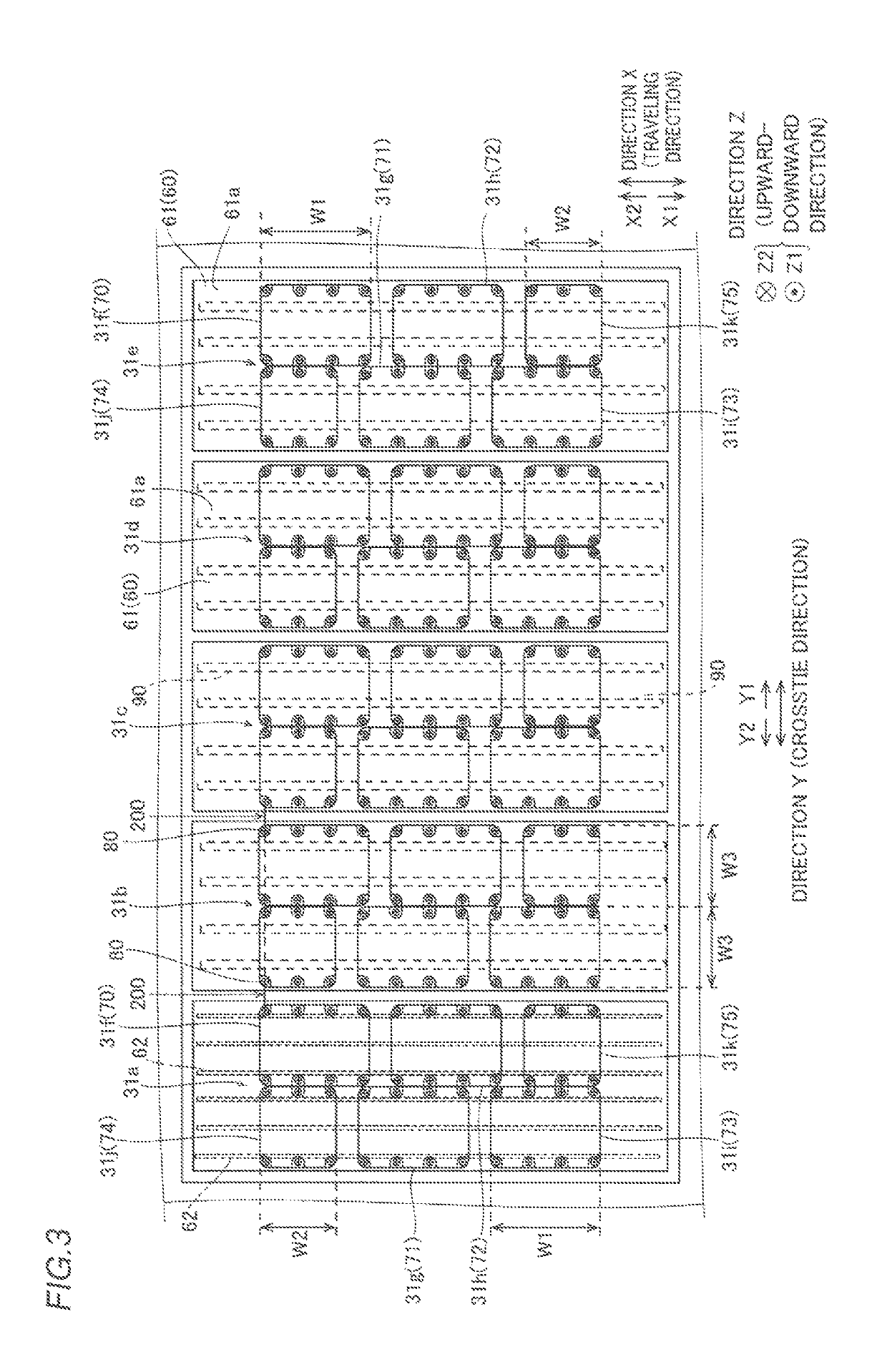
[0092]For example, while the fins (radiation fins 62) with which the second semiconductor switching element overlaps as viewed in the direction (direction Z) orthogonal to the surfaces (61a) of the coolers are different from the fins (radiation fins 62) with which the third semiconductor switching element overlaps as viewed in the direction (direction Z) orthogonal to the surfaces (61a) of the coolers in the aforementioned embodiment, the present invention is not restricted to this. For example, a portion of the fins (radiating fins 62) with which the second semiconductor switching element overlaps as viewed in...


PUM


Abstract

In each of a plurality of semiconductor element groups of a power converter, a second semiconductor switching element and a third semiconductor switching element are shifted from each other in a second direction such that at least a portion of fins with which the second semiconductor switching element overlaps as viewed in a direction orthogonal to surfaces of coolers is different from fins with which the third semiconductor switching element overlaps as viewed in the direction orthogonal to the surfaces of the coolers.

Description

CROSS-REFERENCE TO RELATED APPLICATION[0001]The present application claims priority of Japanese Patent Application No. 2017-219730 filed Nov. 15, 2017, the disclosure of which is hereby incorporated by reference.BACKGROUND OF THE INVENTION[0002]Field of the Invention[0003]The present invention relates to a power converter and a power converter for a railroad vehicle, and more particularly, it relates to a power converter and a power converter for a railroad vehicle, both of which include a plurality of semiconductor element groups each including a plurality of semiconductor switching elements.[0004]of Description the Background Art[0005]A power converter and a power converter for a railroad vehicle, both of which include a plurality of semiconductor element groups each including a plurality of semiconductor switching elements is known in general, as disclosed in Japanese Patent Laid-Open No. 2007-104784.[0006]A power converter disclosed in Japanese Patent Laid-Open No. 2007-104784 i...

Claims


Application Information

Patent Timeline
Patent Type & Authority Patents(United States)
IPC IPC(8): H05K7/20H02M7/00H01L23/367H02M5/458H02M7/487
CPCH02M7/003H05K7/20863H05K7/20909H05K7/20854H05K7/209H01L23/3672H05K7/20918H05K7/20881H05K7/20936H02M7/487H02M5/4585
Inventor TAKIZAWA, MASAMITSUKOBAYASHI, NOBUYUKIMORI, YOSHIONAKAMICHI, SOMATSUI, KOHEI
Owner FUJI ELECTRIC CO LTD
Why Eureka
Try Eureka