Printing device

a printing device and printing technology, applied in printing presses, printed circuits, printing, etc., can solve the problems of conceivably failing cream solder scooping operations, and achieve the effect of reducing the stop time of the device, quick operation, and preventing the next coating material scooping operation

Active Publication Date: 2021-09-14
YAMAHA MOTOR CO LTD
View PDF16 Cites 0 Cited by
  • Summary
  • Abstract
  • Description
  • Claims
  • Application Information

AI Technical Summary

Benefits of technology

[0006]Accordingly, the present disclosure provides a printing device capable of significantly reducing or preventing failure of coating material scooping operation due to an insufficient amount of movement of a coating material scooping unit in the coating material scooping operation.
[0017]According to the present disclosure, as described above, it is possible to provide the printing device capable of significantly reducing or preventing the failure of the coating material scooping operation due to an insufficient amount of movement of the coating material scooping unit in the coating material scooping operation.

Problems solved by technology

However, in the printer described in Japanese Patent No. 5873928, the solder loading and unloading device conceivably moves from the design start position to the design end position and performs the scooping operation, and thus the actual width of the cream solder does not appear to have been taken into account.
In this case, the cream solder scooping operation may conceivably fail due to an insufficient amount of movement of the solder loading and unloading device.

Method used


Image

  • Printing device
  • Printing device
  • Printing device

Examples


modified examples

[0101]The embodiment disclosed this time must be considered as illustrative in all points and not restrictive. The scope of the present disclosure is not shown by the above description of the embodiment but by the scope of claims for patent, and all modifications (modified examples) within the meaning and scope equivalent to the scope of claims for patent are further included.

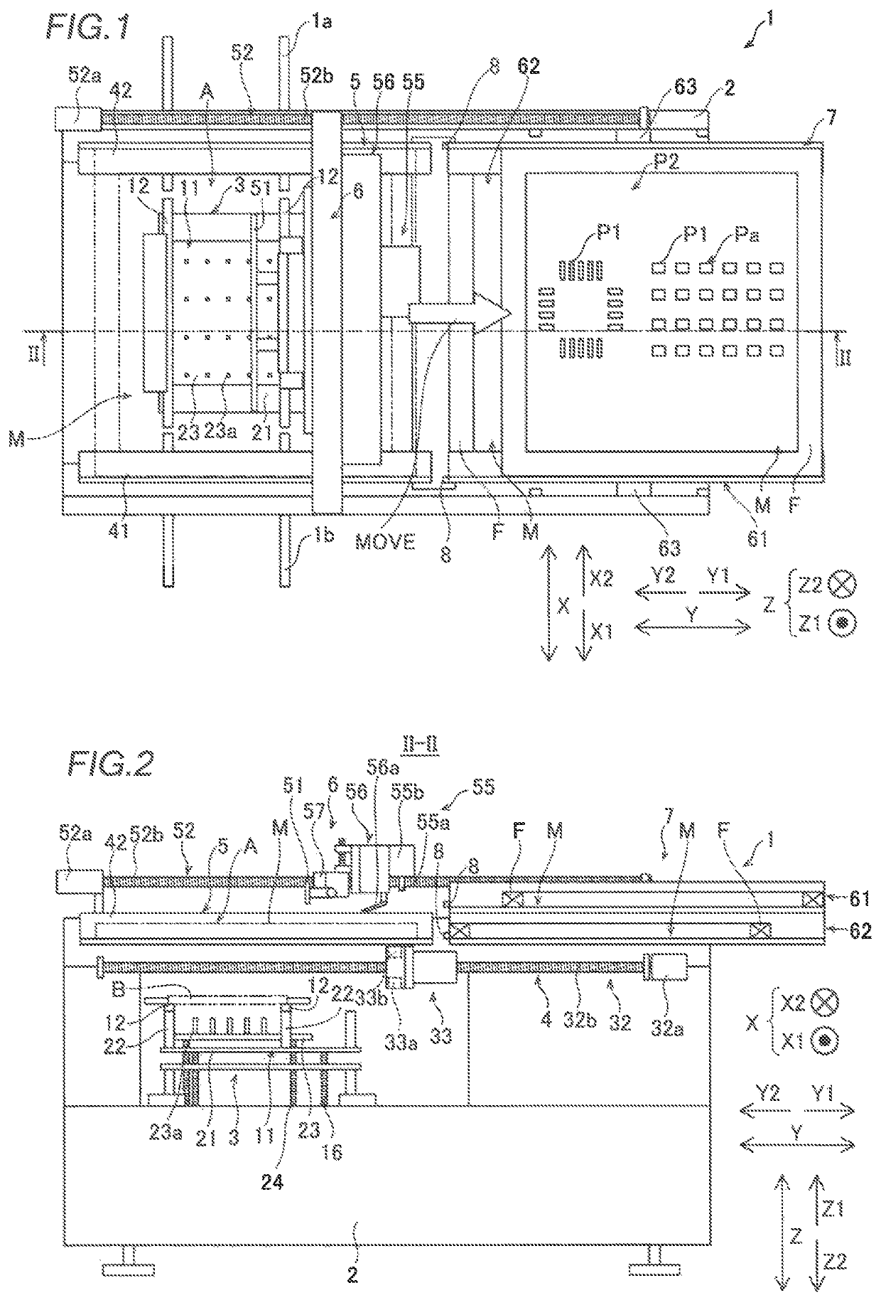
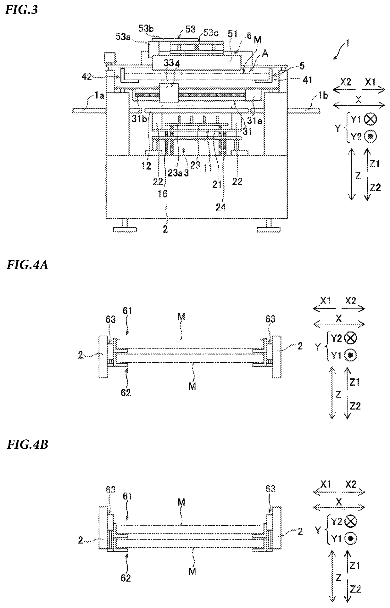
[0102]For example, while the example in which the present disclosure is applied to a printing device that automatically replaces a mask with a mask slider (mask replacer) has been shown in the aforementioned embodiment, the present disclosure is not restricted to this. The present disclosure may be applied to a printing device in which a user manually replaces a mask.

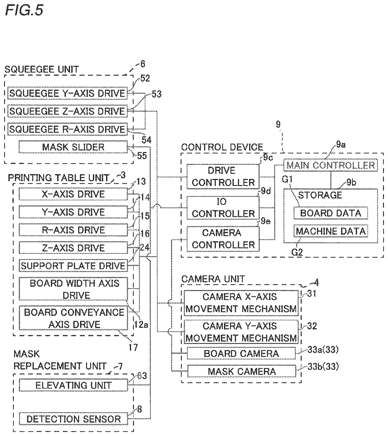
[0103]While the example in which the control device (controller) is configured to acquire the start position of the movement of the solder scooping unit (coating material scooping unit) in the solder scooping operation, the end position of the move...


PUM


Abstract

A printing device includes a controller configured or programmed to acquire, based on a width of a coating material that has been measured, at least one of a start position, an end position, or an amount of movement of a coating material scooping unit in coating material scooping operation.

Description

CROSS-REFERENCE TO RELATED APPLICATION[0001]This application is a National Stage of International Patent Application No. PCT / JP2018 / 021532, filed Jun. 5, 2018, the entire content of which is incorporated herein by reference.BACKGROUNDTechnical Field[0002]The present disclosure relates to a printing device, and more particularly, it relates to a printing device including a coating material scooping unit configured to scoop a coating material on a mask.Background Art[0003]Conventionally, a printing device including a coating material scooping unit configured to scoop a coating material on a mask is known. Such a printing device is disclosed in Japanese Patent No. 5873928, for example.[0004]Japanese Patent No. 5873928 discloses a printer (printing device) configured to print a cream solder on a surface of a printed board by moving the cream solder (coating material) on a mask with a squeegee. This printer includes a solder loading and unloading device (a coating material scooping unit)...

Claims


Application Information

Patent Timeline
Patent Type & Authority Patents(United States)
IPC IPC(8): B41F15/08B41F15/40B41F35/00
CPCB41F15/08B41F15/40B41F35/00B41F15/0881H05K3/1233H05K2203/163H05K3/3457
Inventor FUJIMOTO, TAKESHITOTANI, KATSUMIMIWA, TAKESHISUGAHARA, KAZUYUKI
Owner YAMAHA MOTOR CO LTD
Why Eureka
Try Eureka