Aeroderivative jet engine accessory starter relocation to main shaft—directly connected to HPC shaft

a jet engine and accessory technology, applied in the direction of jet propulsion plants, machines/engines, engine fuctions, etc., can solve the problems of increasing the overall the turbine section cannot rotate the shaft, and the axial shaft is expensive and time-consuming to manufacture and assemble, so as to reduce the cost, complexity and weight of the gas turbine engine.

Active Publication Date: 2019-10-29
GENERAL ELECTRIC CO
View PDF20 Cites 1 Cited by
  • Summary
  • Abstract
  • Description
  • Claims
  • Application Information

AI Technical Summary

Benefits of technology

[0007]The starting system for a gas turbine engine disclosed herein directly couples to a high pressure shaft in the gas turbine engine. In this respect, the TGB, IGB / PTO, radial shaft, and axial shaft are superfluous components and may be removed from the gas turbine engine. As such, starting system disclosed herein reduces the cost, complexity, and weight of the gas turbine engine over conventional starting systems. Moreover, any accessories normally coupled to the TGB, IGB / PTO, radial shaft, and axial shaft may be relocated and powered by one or more electric motors. Furthermore, the starting system disclosed herein may be installed in the field after initial manufacture of the gas turbine engine.

Problems solved by technology

But, the turbine section is unable to rotate this shaft during starting because the combustor is not yet producing exhaust gases.
But, the TGB, IGB / PTO, radial shaft, and axial shaft are expensive and time consuming to manufacture and assemble.
Furthermore, these components increase the overall complexity and weight of the gas turbine engine.

Method used


Image

  • Aeroderivative jet engine accessory starter relocation to main shaft—directly connected to HPC shaft
  • Aeroderivative jet engine accessory starter relocation to main shaft—directly connected to HPC shaft
  • Aeroderivative jet engine accessory starter relocation to main shaft—directly connected to HPC shaft

Examples


Embodiment Construction

[0017]Reference now will be made in detail to embodiments of the invention, one or more examples of which are illustrated in the drawings. Each example is provided by way of explanation of the invention, not limitation of the invention. In fact, it will be apparent to those skilled in the art that various modifications and variations can be made in the present invention without departing from the scope or spirit of the invention. For instance, features illustrated or described as part of one embodiment can be used with another embodiment to yield a still further embodiment. Thus, it is intended that the present invention covers such modifications and variations as come within the scope of the appended claims and their equivalents.

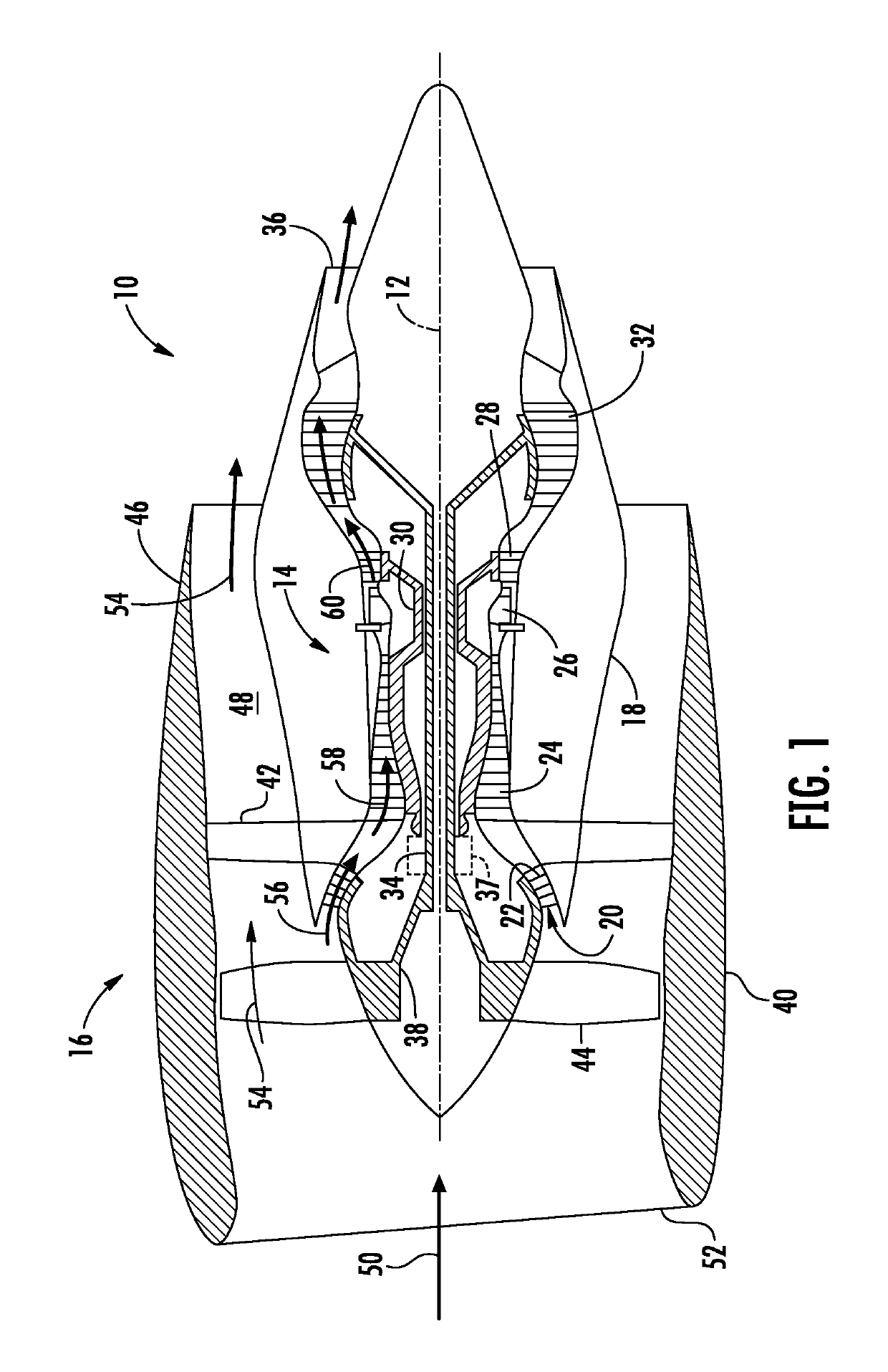
[0018]Referring now to the drawings, FIG. 1 illustrates a cross-sectional view of one embodiment of a turbofan gas turbine engine 10 (“turbofan 10”) that may be utilized within an aircraft in accordance with aspects of the present subject matter, with the t...


PUM


Abstract

In one aspect, the present disclosure is directed to a gas turbine starting system that includes a shaft coupling a compressor and a turbine. An annular housing extends circumferentially around the shaft such that the annular housing defines a compartment. A flange extends radially outward from the annular housing for mounting the annular housing to a stationary wall. A starter is positioned in the compartment. A collar rotatably couples to the annular housing and selectively couples to the starter. The collar includes a radially inner surface having a plurality of splines for engaging the shaft. The starter, when activated, rotates the collar, which rotates the shaft to start the gas turbine.

Description

FIELD OF THE INVENTION[0001]The present subject matter relates generally to a gas turbine engine and, more particularly, to a starting system for a gas turbine engine.BACKGROUND OF THE INVENTION[0002]Gas turbine engines typically include a compressor section, a combustor, and a turbine section. A rotor shaft rotatably couples the compressor section and the turbine section. In this respect, the compressor compresses air entering the gas turbine engine. This compressed air mixes with fuel in the combustor to form an air and fuel mixture, which produces hot exhaust gases when ignited. These hot exhaust gases then flow through the turbine section before exiting the gas turbine engine. The turbine section extracts kinetic energy from the exhaust gases, which, in turn, rotates the rotor shaft. The rotation of the rotor shaft provides the necessary mechanical energy to the compressor section to compress the incoming air.[0003]In order to start the gas turbine engine, it is necessary to rot...

Claims


Application Information

Patent Timeline
Patent Type & Authority Patents(United States)
IPC IPC(8): F02C7/275F02C7/268F02C7/266F02C7/32F02C3/04
CPCF02C7/275F05D2260/85F02C3/04F05D2220/766F02C7/268F02C7/266F02C7/32F02C7/27F02C7/277
Inventor SZCZEPANOWSKI, PAWELGOLDYN, MATEUSZ
Owner GENERAL ELECTRIC CO
Why Eureka
Try Eureka