Axle disconnect assembly with directional roller clutch

a technology of directional roller and assembly, which is applied in the direction of interengaging clutches, couplings, tractors, etc., can solve the problems of reducing the efficiency of the assembly process, requiring considerable extra space for the system, and not providing the modular arrangement necessary for assembly and repair, etc., to achieve the effect of convenient assembly, compact construction, and simple design

Inactive Publication Date: 2008-09-04
DANA AUTOMOTIVE SYST GRP LLC
View PDF19 Cites 13 Cited by
  • Summary
  • Abstract
  • Description
  • Claims
  • Application Information

AI Technical Summary

Benefits of technology

[0009]Therefore, the present invention provides substantially improved packaging of the axle disconnect assembly providing compact, yet robust arrangement of the axle disconnect arrangement. The axle disconnect assembly of the present invention is simple in design, compact in construction and economical to package and manufacture. Thus, the present invention reduces cost, complexity and weight of the axle disconnect assembly.

Problems solved by technology

This conventional system has the drawback of an externally mounted vacuum motor that requires considerable extra space particularly when vehicle suspension travel is taken into account.
The use of an externally mounted vacuum motor also necessitates the use of a fork shift assembly which adds to the cost and complexity of the prior art arrangement exemplified by this system.
Moreover, such prior art axle disconnect systems do not provide a modular arrangement necessary for easy of manufacture, assembly and repair.
Consequently these prior art arrangements are also complex and expensive to produce particularly when the difficulty of assembly is taken into account.
Thus, the axle disconnect assemblies of the prior art, including but not limited to those discussed above, are susceptible to improvements that may enhance their performance and cost.

Method used


Image

  • Axle disconnect assembly with directional roller clutch
  • Axle disconnect assembly with directional roller clutch
  • Axle disconnect assembly with directional roller clutch

Examples


Embodiment Construction

[0014]The preferred embodiments of the present invention will now be described with the reference to accompanying drawing.

[0015]For purposes of the following description, certain terminology is used in the following description for convenience only and is not limiting. The words such as “front” and “rear”, “left” and “right”, “inboard” and “outboard”, “inwardly” and “outwardly” designate directions in the drawings to which reference is made. The words “smaller” and “larger” refer to relative size of elements of the apparatus of the present invention and designated portions thereof. The terminology includes the words specifically mentioned above, derivatives thereof and words of similar import. Additionally, the word “a”, as used in the claims, means “at least one”.

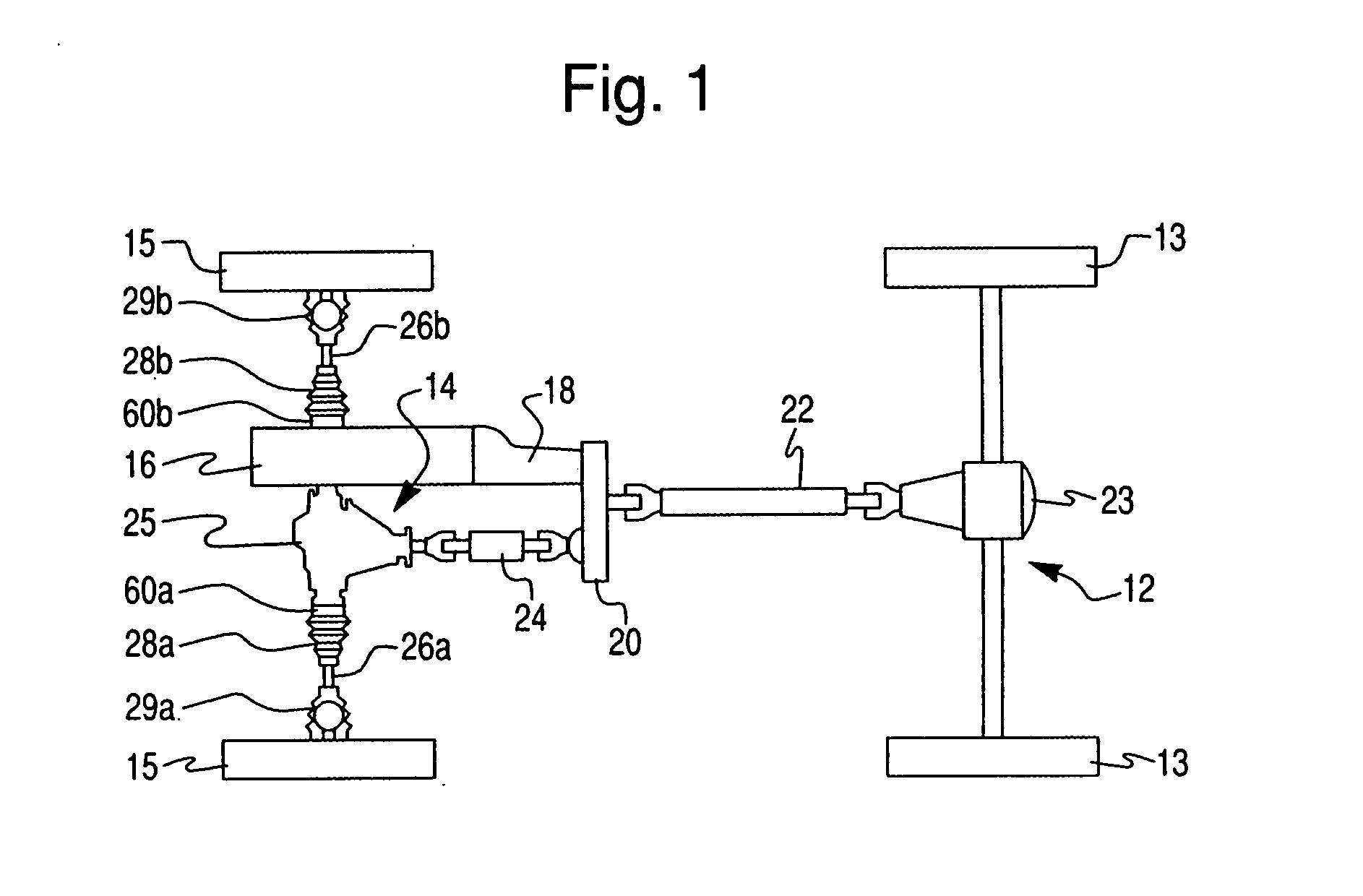
[0016]Referring to FIG. 1 of the drawings, a preferred embodiment of a part-time all-wheel-drive power transmission system of the present invention, generally denoted by reference numeral 10, for use in a conventional moto...


PUM


Abstract

An axle disconnect assembly comprises a shaft extending axially along a central axis, a universal joint including an outer drive member having a substantially annular axial flange extending axially outwardly from the outer drive member coaxially with the central axis so as to form an annular space between the axial flange and the shaft, and a directional roller clutch disposed in the annular space. The directional roller clutch is provided for selectively drivingly coupling the shaft to the outer drive member of the universal joint. The directional roller clutch includes a plurality of rolling elements provided between the outer and inner race members. The rolling elements of the directional roller clutch radially support the outer drive member of the universal joint for rotation about to the shaft.

Description

BACKGROUND OF THE INVENTION[0001]1. Field of the Invention[0002]The present invention relates to axle disconnect assemblies in general and, more particularly, to an axle disconnect assembly including a directional roller clutch.[0003]2. Description of the Prior Art[0004]It is known to provide a part time all-wheel-drive vehicle that includes an axle disconnect mechanism in a front axle assembly. Such axle disconnect mechanisms include a vacuum motor and a shift fork assembly. The vacuum motor communicates with a vacuum source that is controlled by a two position solenoid valve. The fork shift assembly under control of the vacuum motor controls the axial shifting of a clutch collar between positions corresponding to coupled and uncoupled operating modes. This conventional system has the drawback of an externally mounted vacuum motor that requires considerable extra space particularly when vehicle suspension travel is taken into account. The use of an externally mounted vacuum motor a...

Claims


Application Information

Patent Timeline
Patent Type & Authority Applications(United States)
IPC IPC(8): F16D15/00F16D11/04F16D3/34
CPCF16D28/00F16D41/088F16D41/067F16D27/112
Inventor HEISEY, ZACHARY M.SOMMER, RANDY L.
Owner DANA AUTOMOTIVE SYST GRP LLC
Why Eureka
Try Eureka