Sensor bracket

a technology of sensor brackets and brackets, which is applied in the direction of camera body details, camera filters, instruments, etc., can solve the problems of unstable mounting of the camera brackets, the unstable up-down direction of the camera body on the board,

Active Publication Date: 2019-10-29
HONDA MOTOR CO LTD
View PDF12 Cites 1 Cited by
  • Summary
  • Abstract
  • Description
  • Claims
  • Application Information

AI Technical Summary

Benefits of technology

[0010]According to the sensor bracket of the present disclosure, when the operator attaches the sensor to the bracket body, the spring member abuts against the sensor from a first position and is defamed during the further movement to a second position, which define a deformation range of the spring member, i.e., a displacement distance of the defaming end of the spring member due to the engagement movement in the engagement direction; however, the restriction portion is provided such that it restricts the deformation range of the spring member within the predetermined elastic defamation range considered to be acceptable to the spring member because the restriction portion is configured to abut the sensor and prevents further deformation of the spring member when the spring member reaches the second position. Accordingly, the biasing force of spring member can be prevented from decreasing due to plastic deformation and the sensor can be mounted on the bracket body in a stable manner.
[0012]According to such a configuration, since the abutting portion of the restriction portion of the bracket body has the same shape as the shape of the sensor, when the sensor is mounted on the bracket body, the sensor and the bracket body are abutted against each other in a wide area. With the above, the pressure of the sensor during attachment does not concentrate on a specific position and the sensor and the bracket body can be prevented from becoming damaged.

Problems solved by technology

Since the flat spring of Japanese Unexamined Patent Application Publication No. 2013-203250 biases the on-board camera body only in the front direction, the on-board camera body may be unstable in the up-down direction.
However, as in the bracket of Japanese Unexamined Patent Application Publication No. 2013-203250, in a case in which an adhesion portion adhered to a surface of a piece of glass is famed in a planar shape, when the on-board camera body is attached, the spring is pressed hard in the up-down direction and becomes elastically deformed, such that the biasing force of the spring becomes weak disadvantageously causing the on-board camera to be mounted on the bracket in an unstable manner.

Method used


Image

  • Sensor bracket
  • Sensor bracket
  • Sensor bracket

Examples


Embodiment Construction

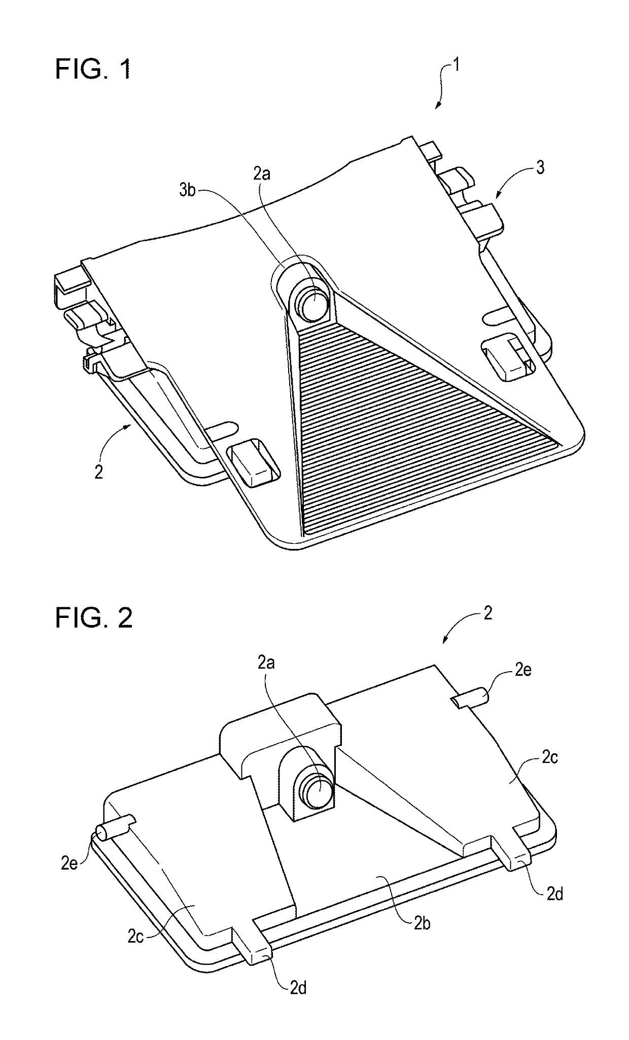
[0019]FIG. 1 illustrates a configuration in which a camera corresponding to a sensor of the present disclosure that detects the surroundings of a vehicle is mounted on a sensor bracket of the present disclosure. Hereinafter, the above configuration is referred to as a camera unit 1.

[0020]FIG. 1 is a perspective view of the camera unit 1 viewed obliquely from above. The camera unit 1 includes a camera 2 that is a sensor that performs imaging of an image in front of the vehicle, and a bracket 3 that is fixed to the windshield of the vehicle by being adhered thereon. Note that, hereinafter, description is given while the front of the vehicle is a front direction (a front side).

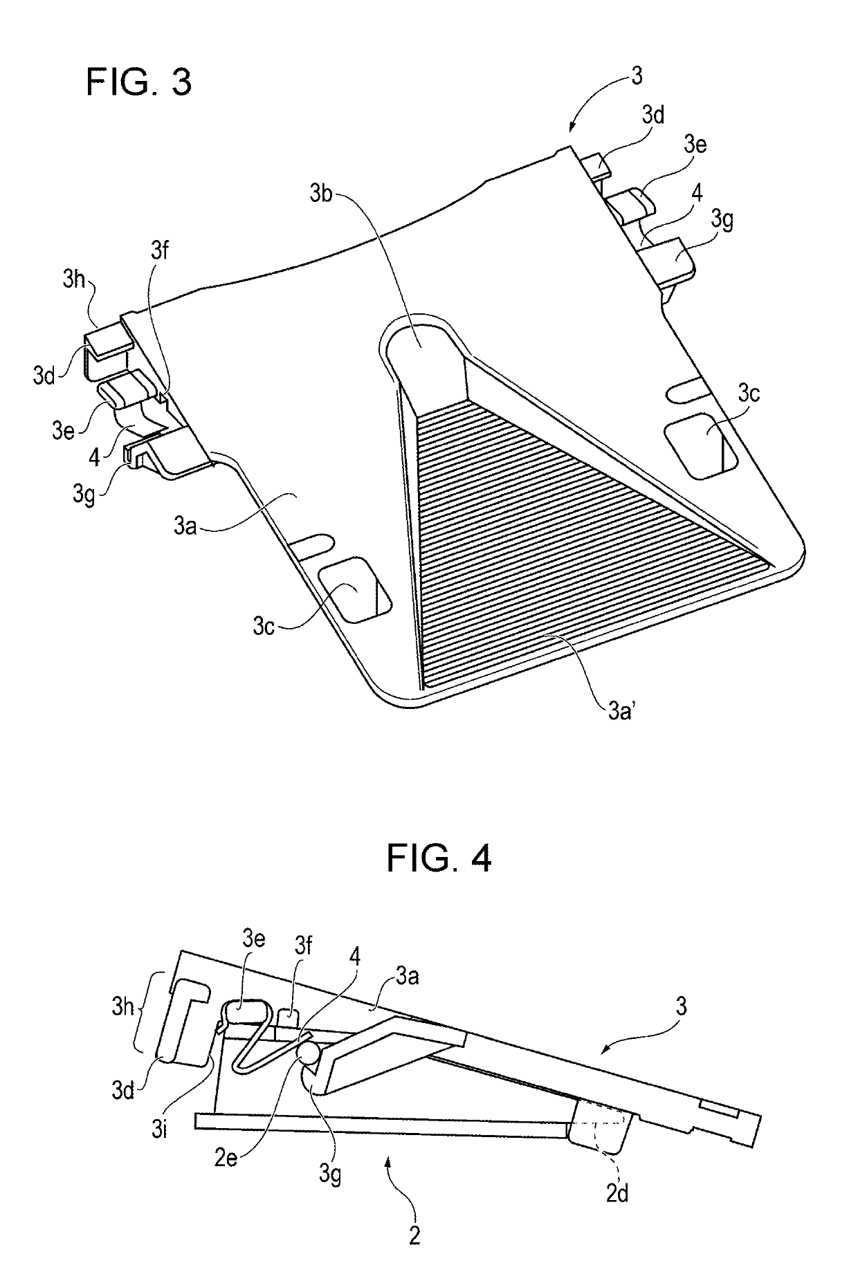
[0021]As illustrated in the drawings, the camera 2 is mounted on the bracket 3 from a lower side of the bracket 3 with an engaging mechanism described later. An opening 3b into which a lens 2a of the camera 2 is inserted is provided on an upper surface of the bracket 3. With the above, the camera 2 is capable of ...


PUM


Abstract

A sensor bracket includes a bracket on which a camera detecting a state around the vehicle is mounted, a planar portion that holds the camera to the bracket by engaging with an engagement protrusion of the camera, a flat spring that biases the camera in a direction that maintains an engaged state of the camera by abutting against the camera when the camera is mounted on the bracket, a projecting structure of the bracket that restricts a defamation range of the flat spring displaced in an engagement direction of the engagement protrusion within an elastic deformation range when the engagement protrusion is engaged with the planar portion while the camera is abutted against the flat spring.

Description

CROSS REFERENCES TO RELATED APPLICATIONS[0001]The present application claims priority under 35 U.S.C. § 119 to Japanese Patent Application No. 2016-060374, filed Mar. 24, 2016, entitled “Sensor Bracket.” The contents of this application are incorporated herein by reference in their entirety.BACKGROUND1. Field[0002]The present disclosure relates to a sensor bracket used to attach an on-board camera or the like.2. Description of the Related Art[0003]Hitherto, a technique is known that accurately detects an obstacle and a pedestrian, a position of a traffic lane, whether a headlight of an oncoming vehicle is on, and the like by performing imaging of a portion in front of a vehicle with an on-board camera. In such a case, the on-board camera is mounted on a bracket that is attached to a windshield.[0004]For example, in Japanese Unexamined Patent Application Publication No. 2013-203250, while bosses of an on-board camera main body are hooked to hook-shaped portions, the on-board camera m...

Claims


Application Information

Patent Timeline
Patent Type & Authority Patents(United States)
IPC IPC(8): G03B17/56B60R11/04F16M13/02B60R11/00
CPCF16M13/02G03B17/561B60R11/04B60R2011/0084B60R2011/0026B60R2011/0059B60R2011/0075G03B11/045G03B17/02
Inventor KASAI, KEITATOKIWA, MITSURUMATORI, TADAHIROOHMOTO, TAKAHIRO
Owner HONDA MOTOR CO LTD
Why Eureka
Try Eureka