Electronic device having half mirror on front face

a technology of electronic devices and mirrors, applied in the field of half mirrors, can solve the problems of increasing the static electricity being charged in the half mirror, deteriorating the quality of the half mirror as decorative panel, and reducing the service life of the half mirror, so as to prevent further deformation, and reduce the cost of maintenance.

Inactive Publication Date: 2006-01-05
ORION ELECTRIC CO LTD
View PDF1 Cites 2 Cited by
  • Summary
  • Abstract
  • Description
  • Claims
  • Application Information

AI Technical Summary

Benefits of technology

[0017] According to the fourth aspect of the invention, the elastic conductive member is disposed so that when it is pressed against the mounting panel, it is partially overhung from an end of the mounting panel, so that the overhang portion of the compressed elastic conductive member is not in the range of the contact surface and thus not compressed. Therefore, when the elastic conductive member is compressed by the mounting panel, the area in contact with the contact surface is compressed but the overhang area is not compressed, so that the overhang portion is deformed in an arc shape and expanded toward a specific direction. Since the upper wall of the guide panel is positioned in the area toward which the overhang portion is deformed in an arc shape, the deformed portion is blocked by the upper wall which prevents further deformation. Thus, the elastic conductive member is prevented from being deformed in an unspecific direction and coming into contact with the external connecting terminal disposed close to the contact surface on the mounting panel. Furthermore, the overhang portion of the elastic conductive member which is not compressed by the contact surface looks swollen. Since this portion is positioned in an inner side of the electronic device from the mounting panel, it is possible to estimate how much the elastic conductive member is compressed by visually confirming the size of the swollen portion. Therefore, it is possible to easily determine whether the conductive member is suitably compressed or not by visual observation.

Problems solved by technology

However, if the gap is too narrow, the half mirror may still be scratched, but if the gap is too wide, the potential of the static electricity being charged in the half mirror increases, by which the energy of discharge to the metallic conductor becomes too strong, causing even greater burn of the vapor deposited layer of the half mirror and deteriorating the quality of the half mirror as decorative panel.
However, if the gap is too narrow, the half mirror may still be damaged, and if the gap is too wide, the potential of the static electricity being charged in the half mirror increases, by which the energy of discharge to the metallic conductor becomes too strong, causing even further burn of the vapor deposited layer of the half mirror and deteriorating the quality of the half mirror as the decorative panel.

Method used


Image

  • Electronic device having half mirror on front face
  • Electronic device having half mirror on front face
  • Electronic device having half mirror on front face

Examples


first embodiment

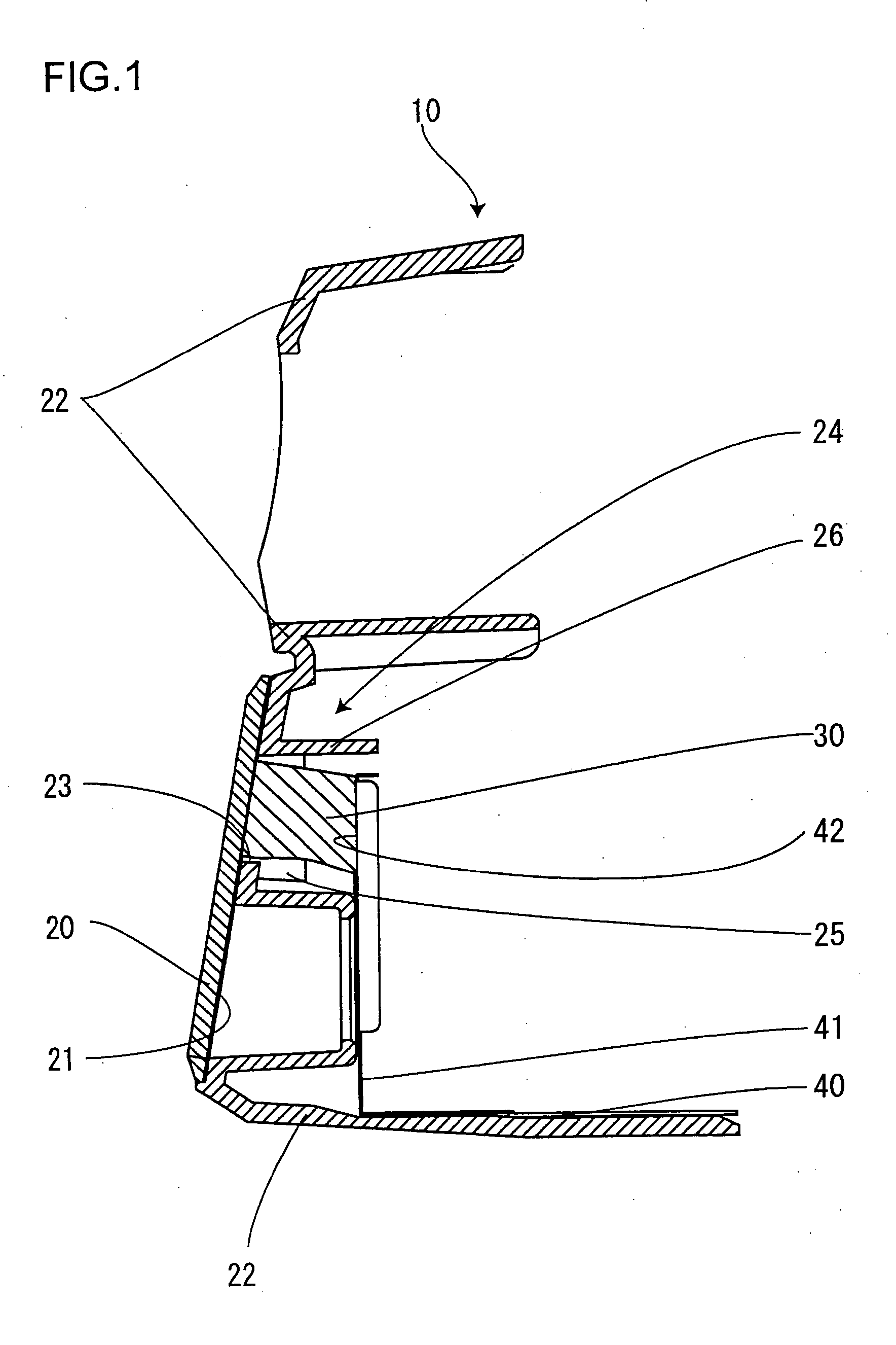
[0026]FIG. 1 is an explanatory cross-sectional view showing a schematic structure of a method for conducting a half mirror and a conductive chassis via an elastic conductive member according to the invention.

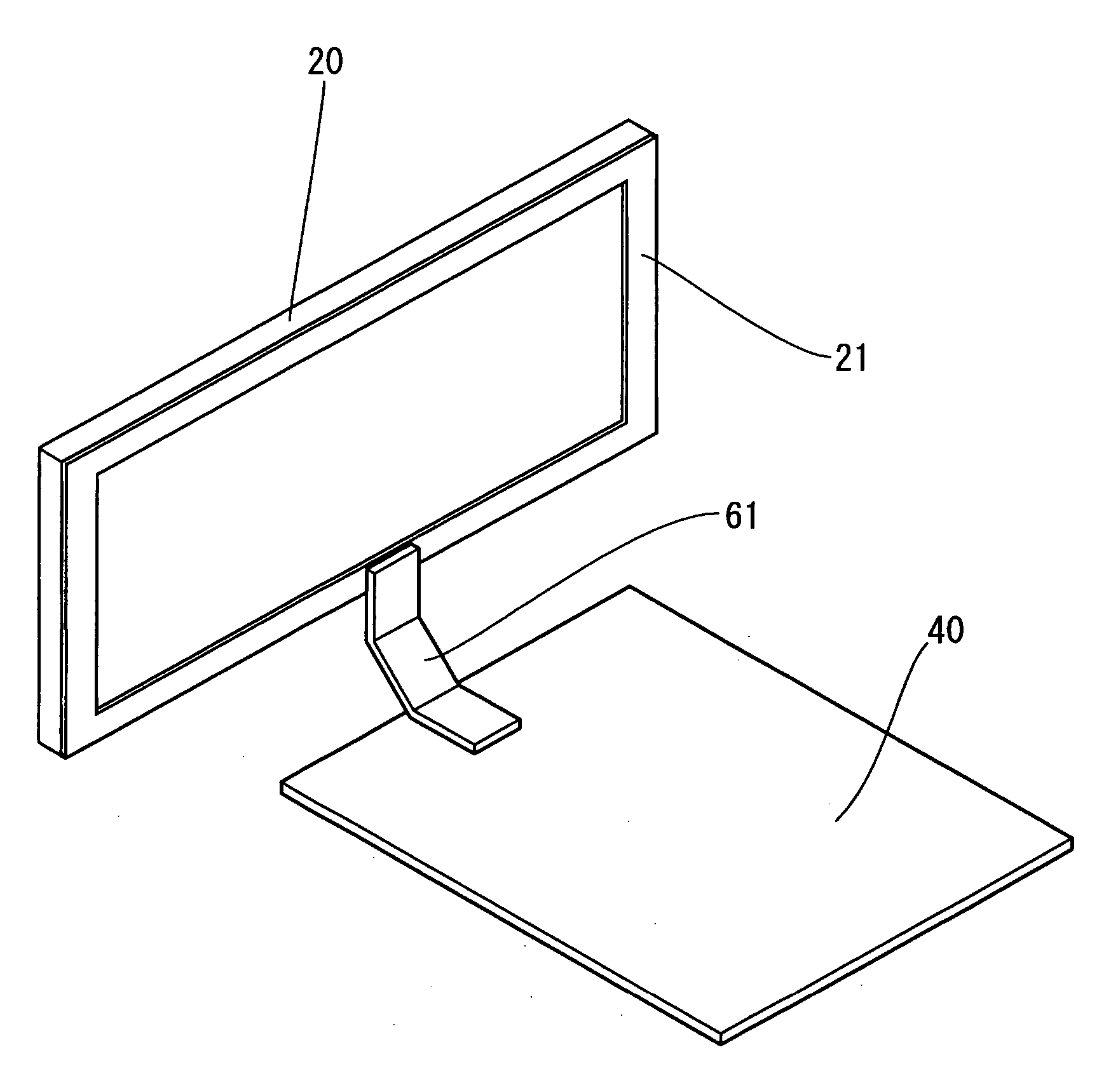
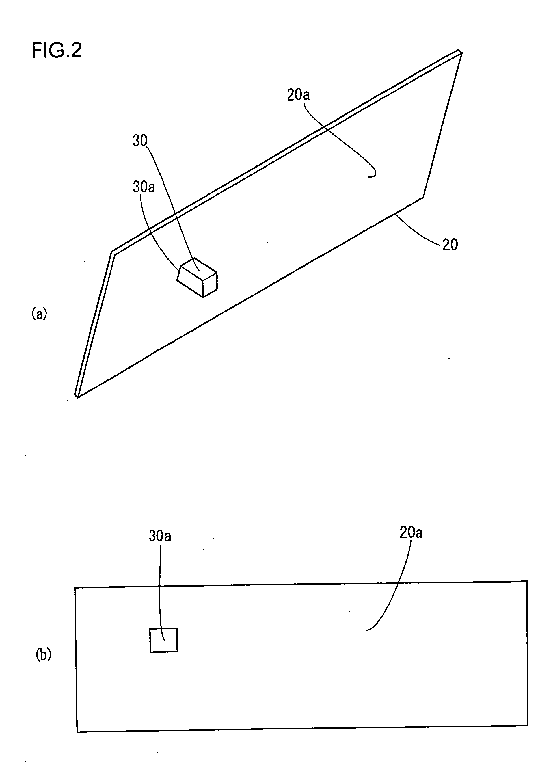
[0027] With reference to FIG. 1, we will explain the structure for providing a ground connection from a half mirror 20 to a conductive chassis 40 so as to prevent static electricity from being charged in the half mirror 20 constituting a part of a decorative panel. The conductive chassis 40 is a metallic panel for mounting a circuit wiring board (not shown) and the like, having an electronic component 50 which is an external connecting terminal such as a jack terminal arranged on a wall surface formed by bending a portion of the conductive chassis upward, and a contact surface 42 to be in contact with an elastic conductive member 30 is arranged on the wall surface of the conductive chassis 40. The elastic conductive member 30 is a conductor for connecting the vapor deposited lay...

second embodiment

[0031] Next, the second embodiment according to the present invention will be described. FIG. 3 is a perspective view showing the through hole and a guide panel provided on a decorative panel through which the elastic conductive member is inserted and supported.

[0032] A through hole 23 for the elastic conductive member 30 is formed to the decorative panel 22, and the decorative panel 22 further has a guide panel 24 projected toward the chassis 40 from the through hole 23. The guide panel 24 has left and right side walls 25 for supporting the left and right sides of the elastic conductive member 30, and an upper wall 26 projected further toward the chassis 40 than the side walls 25. Thus, it becomes possible to pinch using fingers the elastic conductive member 30 from the sides corresponding to the side walls 25, and to insert the member 30 to the hole using the upper wall as a positioning plate defining the vertical position and using the side walls 25 as positioning plates defining...


PUM


Abstract

The invention provides a method for preventing a half mirror used as a decorative panel of an electronic device from being burned by charged static electricity and having deteriorated appearance, by providing a practical method for providing a ground connection of the half mirror using a soft elastic conductive member to prevent the half mirror from being damaged and to enable easy connection with a rough size accuracy. An electronic device comprises a conductive chassis and a half mirror constituting at least a portion of a decorative panel formed on a front face thereof, wherein an elastic conductive member compressed between a vapor deposited layer formed to an inner surface of the half mirror and a contact surface of the chassis is arranged so that a static electricity charged in the half mirror is conducted via the elastic conductive member toward the conductive chassis.

Description

[0001] The present application is based on and claims priority of Japanese patent application No. 2004-194243 filed on Jun. 30, 2004, the entire contents of which are hereby incorporated by reference. BACKGROUND OF THE INVENTION [0002] 1. Field of the Invention [0003] The present invention relates to a half mirror used in a decorative panel of an electronic device, and more specifically, to an art for preventing the deterioration of appearance of the half mirror caused by a vapor deposited layer of the half mirror being burned by static electricity charged in the half mirror. [0004] 2. Description of the Related Art [0005] Heretofore, a half mirror used as a decorative panel disposed on a front face of an electronic device is equipped with a metallic electric conductor functioning as earth to prevent static electricity from being charged in the half mirror. However, to prevent the half mirror from being damaged (scratched) by the hard metallic conductor being in direct contact there...

Claims


Application Information

Patent Timeline
Patent Type & Authority Applications(United States)
IPC IPC(8): G02B27/14
CPCH05K5/0243
Inventor MITOMORI, YASUO
Owner ORION ELECTRIC CO LTD
Why Eureka
Try Eureka