
Power storage unit having reinforcing members in a direction crossing the transverse direction

a technology of power storage unit and transverse direction, which is applied in the direction of cell components, final product manufacturing, sustainable manufacturing/processing, etc., can solve problems similar to the foregoing, and achieve the effect of preventing further deformation of the battery case and preventing damage to the power storage uni

Active Publication Date: 2015-04-14
TOYOTA JIDOSHA KK
View PDF49 Cites 3 Cited by
  • Summary
  • Abstract
  • Description
  • Claims
  • Application Information

AI Technical Summary

Benefits of technology

[0009]The problem to be solved by the present invention lies in that, in a moving conveyance having a power storage unit, the power storage unit may be damaged by the movement of frame members provided in the seats in the event of a crash of the moving conveyance. It is therefore an object of the present invention to provide the power storage unit having a structure capable of preventing damage to the power storage unit disposed between seats adjacent to each other in the transverse direction even when the frame members provided in the seats are moved in the event of a crash of the moving conveyance.
[0012]Accordingly, configuring the battery case of the power storage device to abut against the reinforcing members can prevent further deformation of the battery case toward the battery cells, even when the battery case unit is deformed inwardly due to the abutment of the frame members. This in result can prevent damage to the power storage unit that may be caused by the frame members, more specifically, damage to the battery module that may be caused by the frame members.

Problems solved by technology

It should be noted that a problem similar to the foregoing will arise not only in a vehicle, but also in a moving conveyance with a power storage unit arranged and structured similarly.

Method used


Image

  • Power storage unit having reinforcing members in a direction crossing the transverse direction
  • Power storage unit having reinforcing members in a direction crossing the transverse direction
  • Power storage unit having reinforcing members in a direction crossing the transverse direction

Examples


Embodiment Construction

[0020]In the following, a power storage unit according to an embodiment of the present invention will be described with reference to the drawings. Like reference characters denote like or corresponding parts throughout the above description of the background art and the embodiment hereinbelow, and the same description will not be repeated.

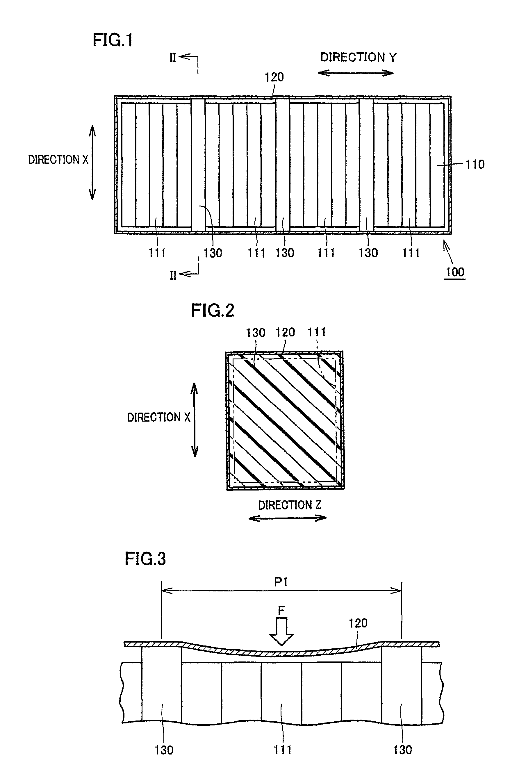
[0021]First, referring to FIGS. 1 to 3, a power storage unit according to the present embodiment will be described.

[0022]Referring to FIGS. 1 and 2, a power storage unit 100 according to the present embodiment is contemplated to be housed in a console box disposed between the driver's seat (see FIG. 7) and the front passenger's seat adjacent to each other in the transverse direction (direction X) of a vehicle, which is a moving conveyance, as described in the background art. Power storage unit 100 includes a battery module 110 housed in a battery case 120.

[0023]This battery module 110 has, as components, a plurality of battery cells 111 stacked and...


PUM

PropertyMeasurementUnit
strengthaaaaaaaaaa
dimensionaaaaaaaaaa
lengthaaaaaaaaaa

Abstract

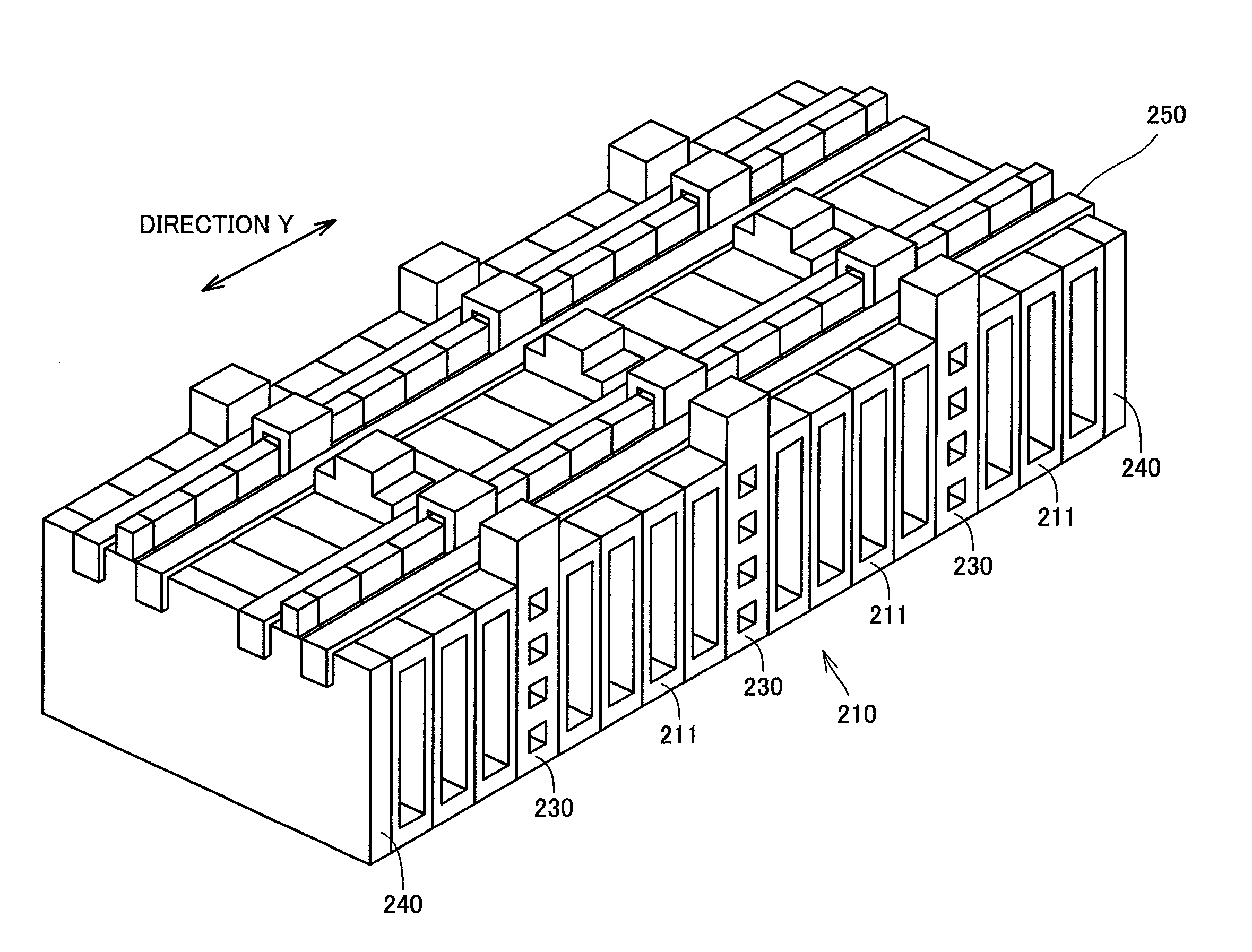
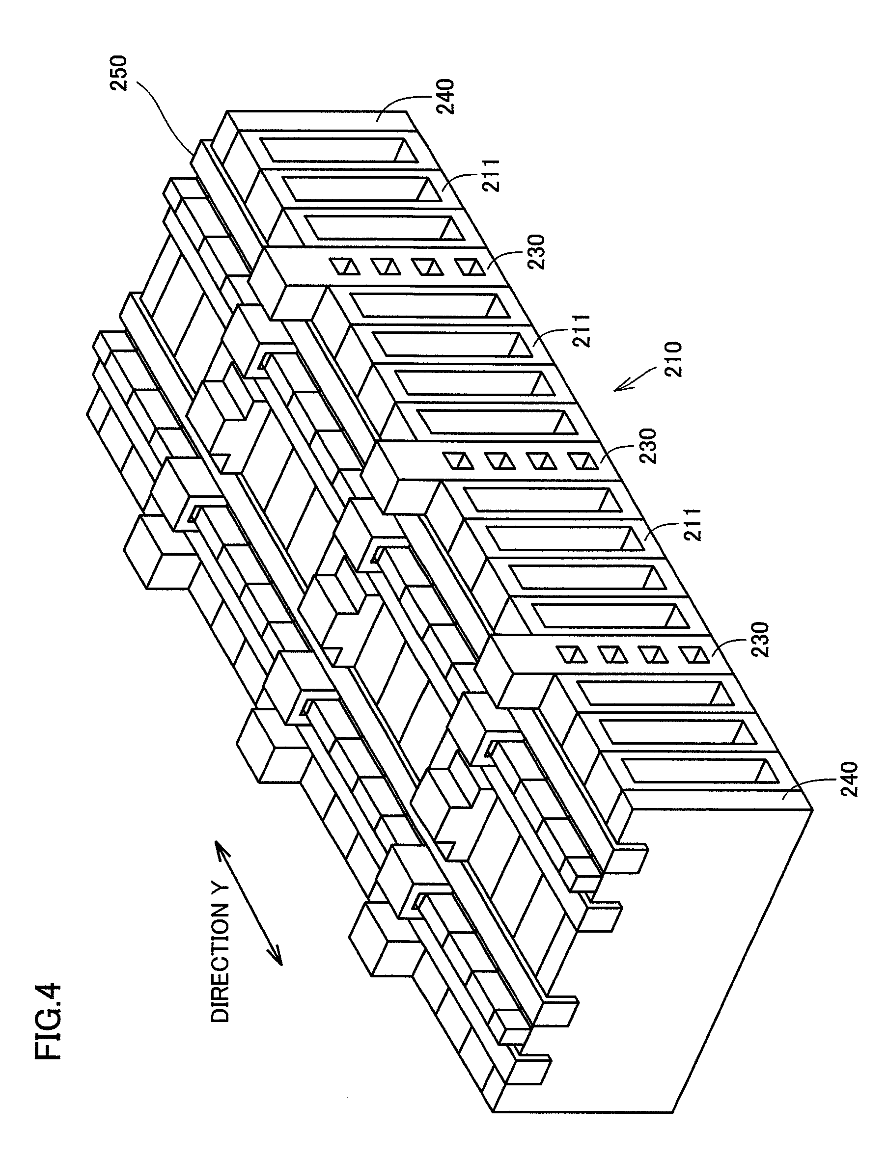
A power storage unit includes a battery module housed in a battery case. The battery module has, as components, a plurality of battery cells stacked and arranged in a direction (direction Y) crossing a transverse direction. Reinforcing members arranged at a predetermined spacing are provided between the battery cells. The power storage unit of this structure can prevent damage to the power storage unit disposed between seats adjacent to each other in the transverse direction, when frame members provided in the seats are moved in the transverse direction in the event of a crash of a moving conveyance.

Description

TECHNICAL FIELD[0001]The present invention relates to a power storage unit, and more particularly to improvements in structure of a power storage unit.BACKGROUND ART[0002]In recent years, as typical examples of moving conveyances, electric vehicles using electric motors as driving sources as well as so-called hybrid cars having multiple kinds of driving sources such as electric motors and gasoline engines have been put to practical use. These electric vehicles and the like are equipped with a power storage unit such as batteries or capacitors for power storage for supplying electricity as energy to the electric motors or the like. For example, secondary batteries that can be repeatedly charged and discharged, such as nickel-cadmium batteries (Ni—Cd batteries), nickel-hydride batteries or lithium-ion batteries, are used as batteries.[0003]In the case where secondary batteries are used as power storages, mounted on a vehicle is a power storage unit including a battery module having a ...

Claims


Application Information

Patent Timeline
Patent Type & Authority Patents(United States)
IPC IPC(8): H01M2/00B60R16/04B60K1/04H01M10/12H01M50/209H01M50/242H01M50/249H01M50/291H01M50/293
CPCH01M2/1072H01M10/12B60K2001/0427H01M2/1083Y02E60/126Y02T10/7016Y02T90/34B60L3/0007B60L3/04B60L58/21B60L58/26B60L50/64Y02E60/10Y02T10/70Y02T90/40Y02P70/50H01M50/293H01M50/249H01M50/209H01M50/291H01M50/242
Inventor SHISHIDO, TOMOHIKONORITAKE, YOSHINORIMATSUMOTO, KIYOSHI
Owner TOYOTA JIDOSHA KK
Learn More