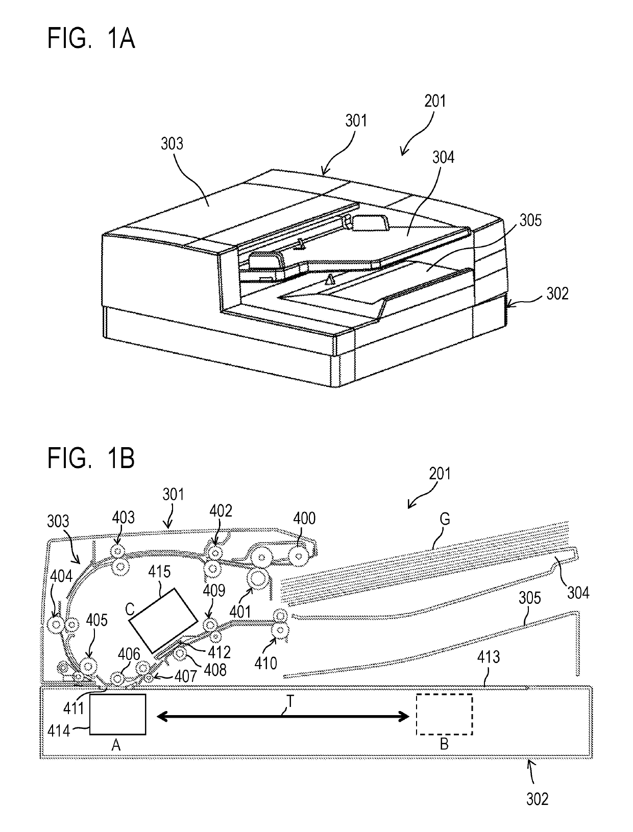
Image reading apparatus with a resinous conductive sheet
a reading apparatus and conductive sheet technology, applied in the field of image reading apparatus, can solve the problems of floating dirt, original itself generating paper dust as the floating dirt, and no consideration given to the adhesion of adhesive dirt on the surface of platen glass, so as to reduce the adhesion of floating dirt and adhesive dir
- Summary
- Abstract
- Description
- Claims
- Application Information
AI Technical Summary
Benefits of technology
Problems solved by technology
Method used
Image

Examples
first embodiment
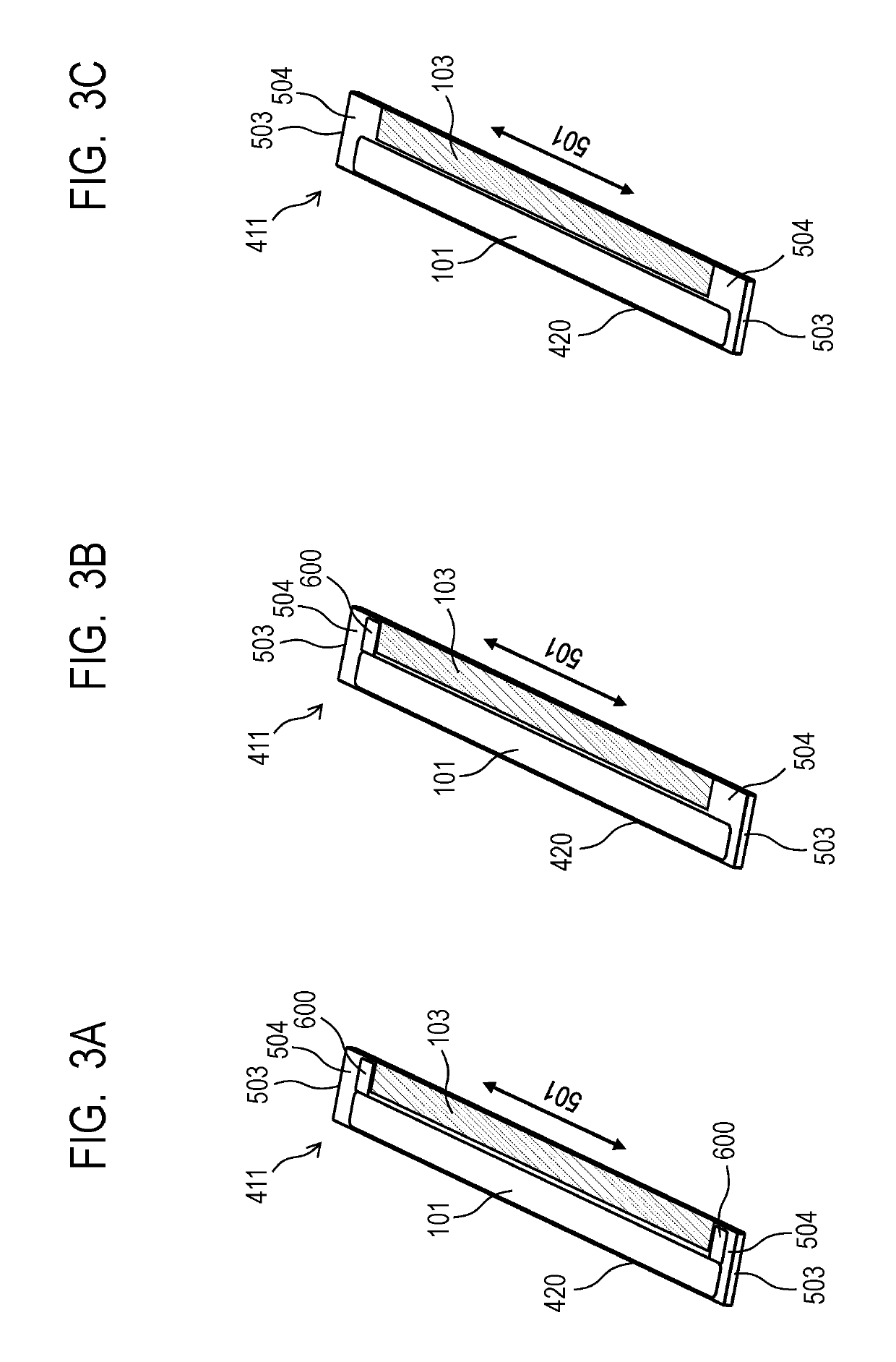
[0075]That is, in the first embodiment illustrated in FIG. 3A, the adjustment member 600 is provided at a vicinity of each end portion in the main scanning direction 501 on the original-side surface of the first platen glass 411.
second embodiment
[0076]Meanwhile, in the second embodiment illustrated in FIG. 3B, the adjustment member 600 is provided only at a vicinity of one of end portions in the main scanning direction 501 on the original-side surface of the first platen glass 411.
third embodiment
[0077]Further, in the third embodiment illustrated in FIG. 3C, the adjustment member 600 is not provided at a vicinity of any end portion in the main scanning direction 501 on the original-side surface of the first platen glass 411.
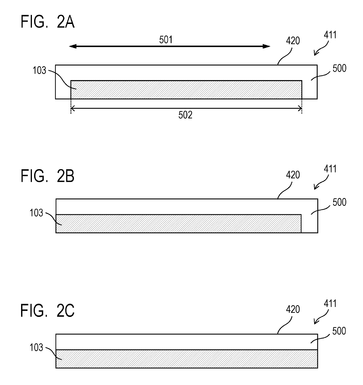
[0078]Here, the third region 504, on which the adjustment member 600 is bonded, is outside an image reading effective region 502 configured to read the image of the original (outside the image reading region). That is, the third region 504 is structured so as to prevent the conveyed original from rubbing against the adjustment member 600.
[0079]Therefore, the adjustment member 600 is not frictionally electrified, and the double-sided adhesive tape, which being the adhesive member, does not need to be the conductive double-sided adhesive tape. Further, it is not necessary to electrically connect the adjustment member 600 to the main body of the image reading apparatus 201 through the grounding member 102.
[0080]The reason why the adjustment member 600 is pro...
PUM
 Abstract
Description
Claims
Application Information
 - R&D
- Intellectual Property
- Life Sciences
- Materials
- Tech Scout
- Unparalleled Data Quality
- Higher Quality Content
- 60% Fewer Hallucinations
Browse by: Latest US Patents, China's latest patents, Technical Efficacy Thesaurus, Application Domain, Technology Topic, Popular Technical Reports.
© 2025 PatSnap. All rights reserved.Legal|Privacy policy|Modern Slavery Act Transparency Statement|Sitemap|About US| Contact US: help@patsnap.com