Electronic telescope

a technology of electronic telescopes and telescopes, applied in the field of electronic telescopes, can solve the problems of increasing manufacturing costs, inconvenient use, and complex manufacturing process, and achieve the effect of increasing manufacturing costs and increasing manufacturing costs

Active Publication Date: 2019-11-05
QUAN XING ELECTRONICS TECH SHENZHEN CO LTD
View PDF8 Cites 7 Cited by
  • Summary
  • Abstract
  • Description
  • Claims
  • Application Information

AI Technical Summary

Benefits of technology

[0029]FIG. 3 is a rear-view diagram illustrating the electronic telescope 1 in FIG. 1. The eyepiece lens 20 has a longitudinal structure and a large area which can fully cover both of the user's eyes, so that it can easily correspond to the eyes of any user. Compared to traditional electronic telescopes / binoculars for two eyes with two independent eyepiece lenses that correspond to two eyes, in the present embodiment, there is no need to adjust the interpupillary distance to accommodate each unique user because the eyepiece lens 20 is a one-piece eyepiece lens with a large covering area. Thus, the electronic telescope 1 is convenient for any user to use (without having to adjust interpupillary distance), and additional components such as adjustment mechanisms for interpupillary distance can be eliminated, simplifying the manufacturing processes and lowering the production cost.

Problems solved by technology

However, everyone's interpupillary distance is different, so that the traditional telescopes / binoculars must include an adjustment mechanism for fine-tuning the interpupillary distance for each user, which may increase manufacturing costs and make the manufacturing process more complex.
Also, it can be inconvenient for the user since the telescope needs to be adjusted prior to each use.
Therefore, to provide a good product design which is convenient for the user and easier to manufacture is an important issue.

Method used


Image

  • Electronic telescope
  • Electronic telescope
  • Electronic telescope

Examples


Embodiment Construction

[0026]The making and using of the embodiments of the electronic telescopes are discussed in detail below. It should be appreciated, however, that the embodiments provide many applicable inventive concepts that can be embodied in a wide variety of specific contexts. The specific embodiments discussed are merely illustrative of specific ways to make and use the embodiments, and do not limit the scope of the disclosure.

[0027]Unless defined otherwise, all technical and scientific terms used herein have the same meaning as commonly understood by one of ordinary skill in the art to which this invention belongs. It should be appreciated that each term, which is defined in a commonly used dictionary, should be interpreted as having a meaning conforming to the relative skills and the background or the context of the present disclosure, and should not be interpreted by an idealized or overly formal manner unless defined otherwise.

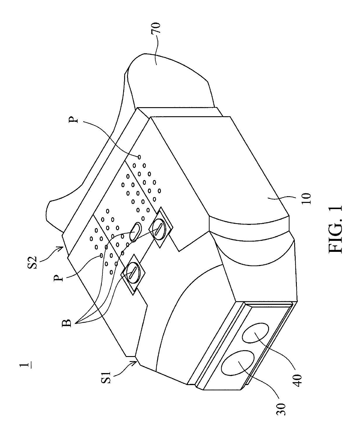
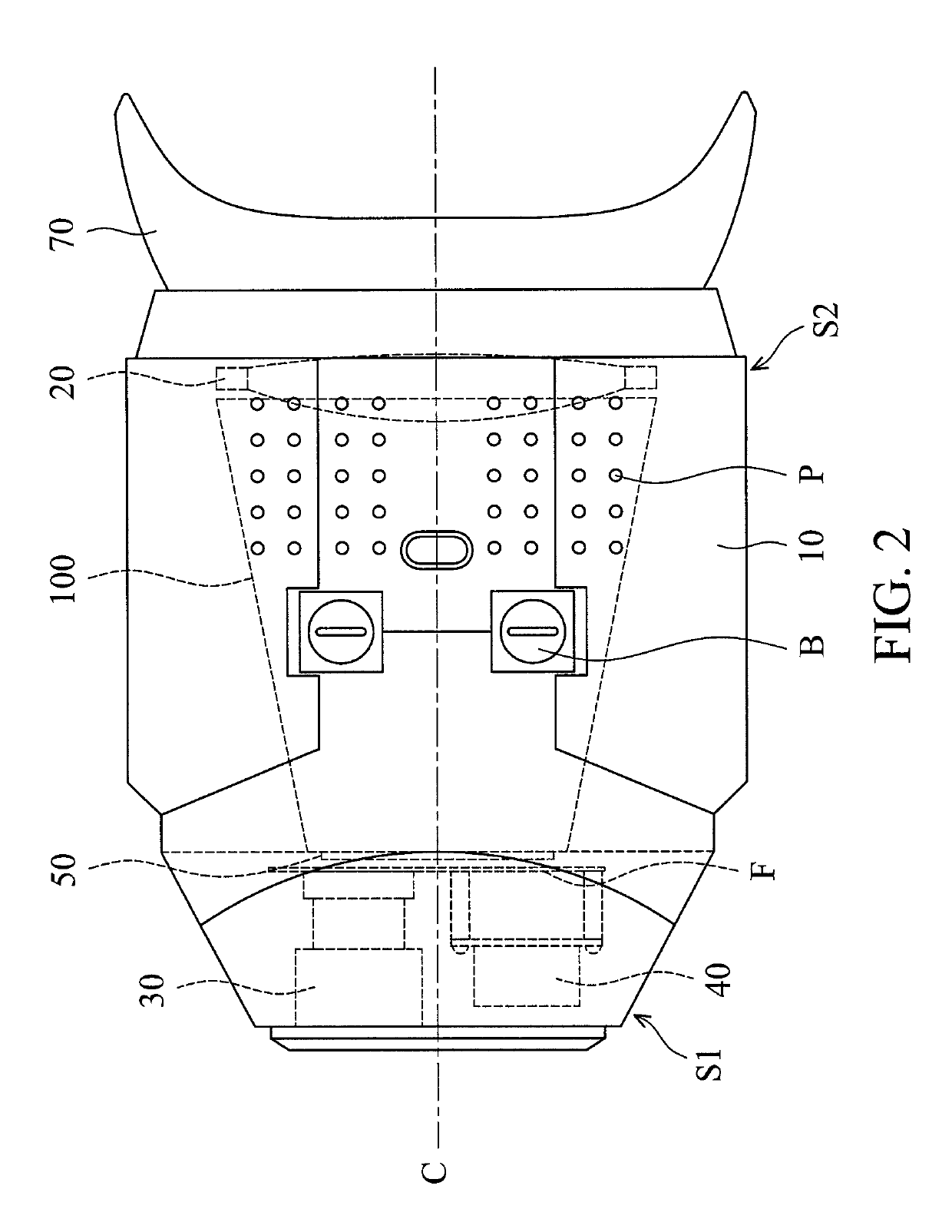
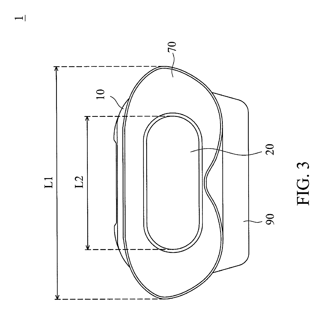
[0028]FIG. 1 is a schematic diagram of an electronic telescope ...


PUM


Abstract

An electronic telescope is provided, including a main body, a lens module, a display module, and a single eyepiece. The main body includes an objective end and an eyepiece end which is opposite to the objective end. The lens module is disposed on the objective end. The display module connects to the lens module and is configured to display an image captured from the lens module. The single eyepiece lens with a single focus has a longitudinal structure and is disposed on the eyepiece end, wherein the eyepiece lens corresponds to the user's two eyes.

Description

BACKGROUND OF THE INVENTIONField of the Invention[0001]The application relates in general to an electronic telescope, and in particular to an electronic telescope that includes a single eyepiece lens.Description of the Related Art[0002]Thanks to the ongoing development of technology, electronic products such as electronic telescopes / binoculars are becoming increasingly versatile. For example, such devices can be used to watch stage performances, to admire natural scenery, and to aid in hunting, and the possible applications of such electronic telescopes grow as newer models continue to display high performance. Traditional telescopes / binoculars for two eyes usually include two independent eyepiece lenses on the eyepiece end. However, everyone's interpupillary distance is different, so that the traditional telescopes / binoculars must include an adjustment mechanism for fine-tuning the interpupillary distance for each user, which may increase manufacturing costs and make the manufactur...

Claims


Application Information

Patent Timeline
Patent Type & Authority Patents(United States)
IPC IPC(8): G02B23/18H04N5/372G02B7/06F21V19/00G02B25/00F21Y105/10F21Y115/10
CPCG02B25/001G02B7/06G02B23/18F21V19/003F21Y2115/10F21Y2105/10H04N5/372G02B23/00G02B23/12H04N25/71
Inventor CHEN, HAN-CHE
Owner QUAN XING ELECTRONICS TECH SHENZHEN CO LTD
Why Eureka
Try Eureka