
Deployable debris protection device for an automotive vehicle

a technology for automobiles and debris protection devices, applied in the field of automotive vehicles, can solve the problems of unwanted and detrimental damage to the exterior of vehicles, stone throws and other road debris, etc., and achieve the effect of reducing the likelihood of a stone throw damaging a vehicl

Active Publication Date: 2019-11-12
GM GLOBAL TECH OPERATIONS LLC
View PDF48 Cites 1 Cited by
  • Summary
  • Abstract
  • Description
  • Claims
  • Application Information

AI Technical Summary

Benefits of technology

The present invention offers a way to prevent stones from causing damage to vehicles without impeding access to them. This results in a safer driving experience and reduces the risk of expensive damage to vehicles.

Problems solved by technology

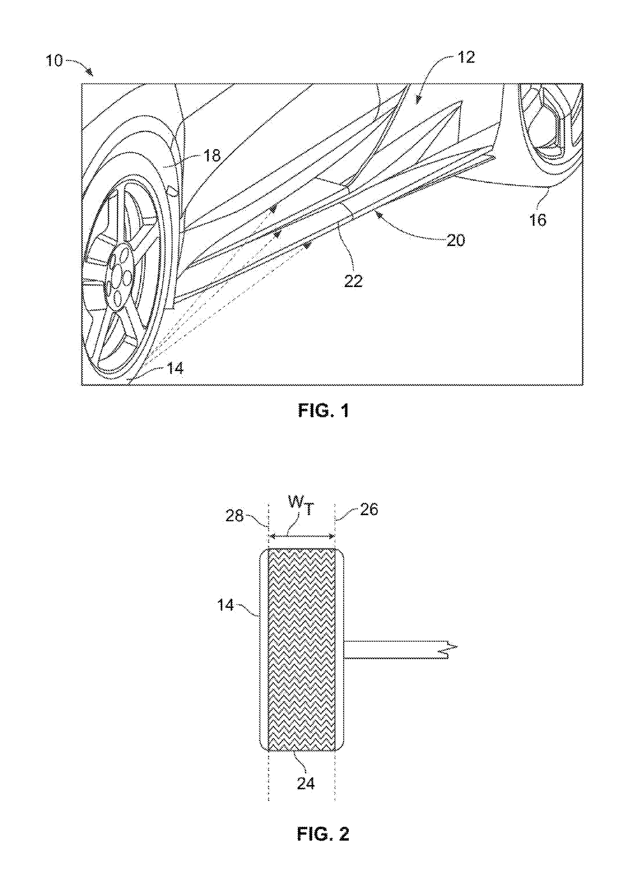
Automotive vehicles frequently travel across road surfaces of varying condition, and therefore may be subjected to stones and other road debris kicked up by vehicle tires.
Collisions between vehicles and such stones or debris may result in undesirable and detrimental marring of the exterior of the vehicles.

Method used


Image

  • Deployable debris protection device for an automotive vehicle
  • Deployable debris protection device for an automotive vehicle
  • Deployable debris protection device for an automotive vehicle

Examples


Embodiment Construction

[0019]Embodiments of the present disclosure are described herein. It is to be understood, however, that the disclosed embodiments are merely examples and other embodiments can take various and alternative forms. The figures are not necessarily to scale; some features could be exaggerated or minimized to show details of particular components. Therefore, specific structural and functional details disclosed herein are not to be interpreted as limiting, but merely as a representative basis for teaching one skilled in the art to variously employ the present invention. As those of ordinary skill in the art will understand, various features illustrated and described with reference to any one of the figures can be combined with features illustrated in one or more other figures to produce embodiments that are not explicitly illustrated or described. The combinations of features illustrated provide representative embodiments for typical applications. Various combinations and modifications of ...


PUM


Abstract

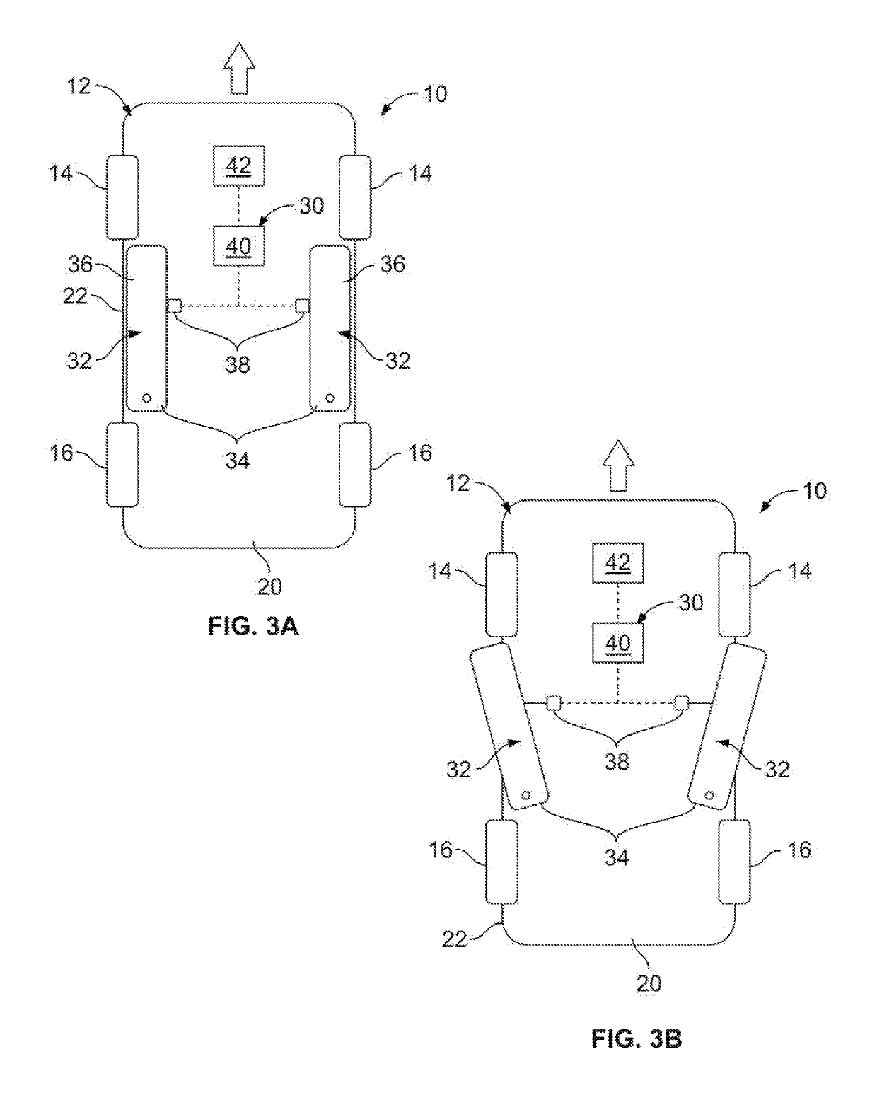
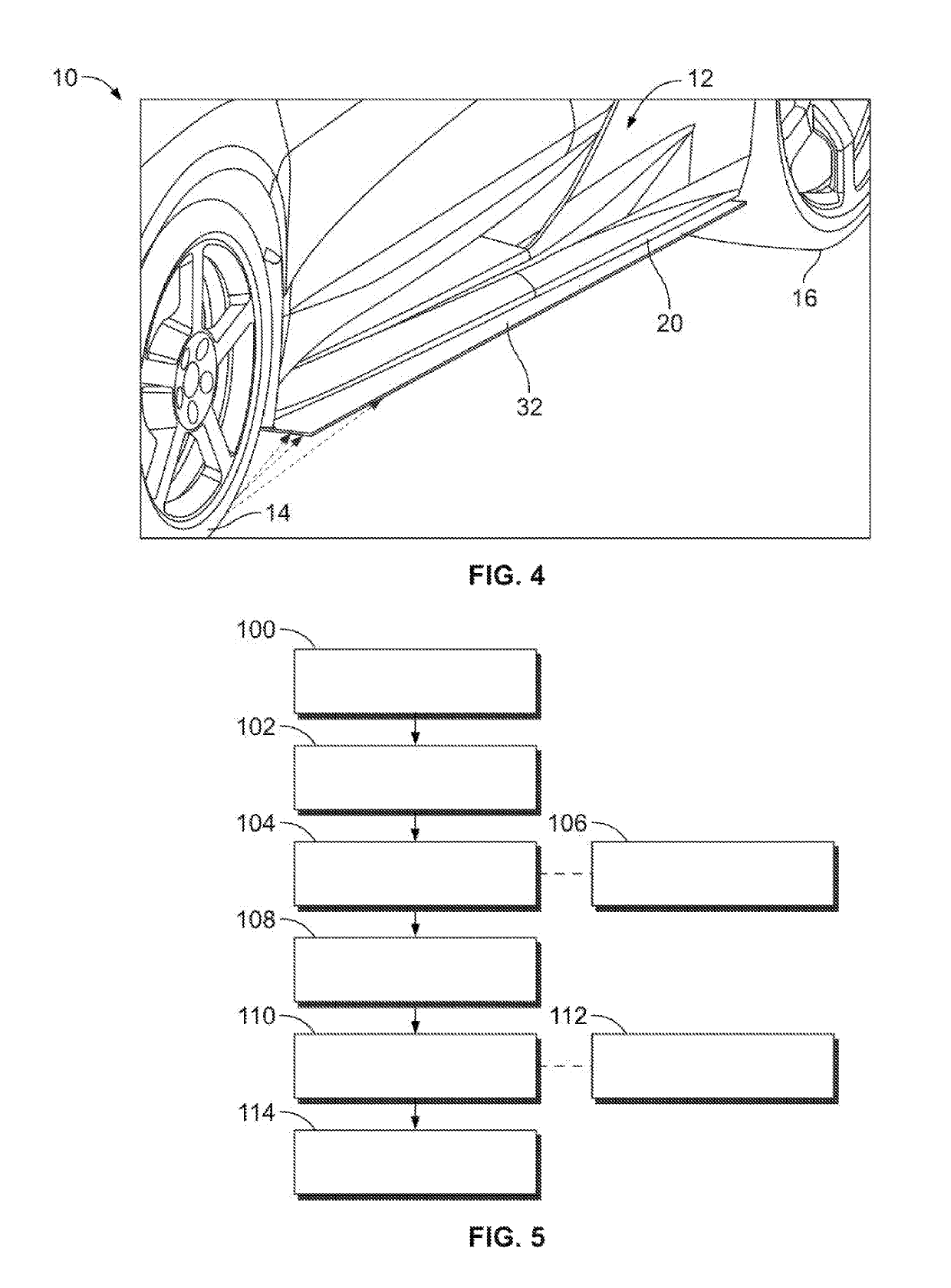
A vehicle includes a body with an underbody portion having an outer periphery. At least one traction wheel is rotatably coupled to the body. The traction wheel has a track width defined by an inboard plane and an outboard plane. A movable panel with an inboard edge and an outboard edge is coupled to the underbody portion. An actuator is coupled to the movable panel and configured to actuate the movable panel between a stowed position and a deployed position. In the deployed position the outboard edge projects outboard of the outboard plane of the track width, and in the stowed position the outboard edge is retracted within the outer periphery of the underbody portion. A controller is configured to, in response to an operating condition being satisfied during a drive cycle, control the actuator to actuate the movable panel from the stowed position to the deployed position.

Description

TECHNICAL FIELD[0001]The present disclosure relates to automotive vehicles, and more particularly to body structures for automotive vehicles.INTRODUCTION[0002]Automotive vehicles frequently travel across road surfaces of varying condition, and therefore may be subjected to stones and other road debris kicked up by vehicle tires. Collisions between vehicles and such stones or debris may result in undesirable and detrimental marring of the exterior of the vehicles.SUMMARY[0003]A vehicle according to the present disclosure includes a body with an underbody portion. The underbody portion has an outer periphery. The vehicle also includes at least one traction wheel which is rotatably coupled to the body. The traction wheel has a track width defined by an inboard plane and an outboard plane. The vehicle additionally includes a movable panel movably coupled to the underbody portion. The movable panel has an inboard edge and an outboard edge. The movable panel is movable between a stowed po...

Claims


Application Information

Patent Timeline
Patent Type & Authority Patents(United States)
IPC IPC(8): B60R19/00B60R19/54B62D25/20
CPCB62D25/2072B60R19/54B60R2019/002
Inventor BOSCO, ANTHONY A.
Owner GM GLOBAL TECH OPERATIONS LLC
Learn More