
Steering centering/damping mechanism for a steerable heavy-duty vehicle axle/suspension system

a technology of steering centering and suspension system, which is applied in the direction of suspension, steering parts, vehicle components, etc., can solve the problems of excessive wear on the tires of the steerable axle/suspension system, low centering force of the coil over stabilizer shocks on the driver side and curb side steering assembly of the axle/suspension system, and the wheel wobble or shimmy of the coil over stabilizer shocks, etc., to reduce wheel wobble, increase the steering angle, and reduce tire s

Active Publication Date: 2019-11-12
HENDRICKSON USA L L C
View PDF43 Cites 2 Cited by
  • Summary
  • Abstract
  • Description
  • Claims
  • Application Information

AI Technical Summary

Benefits of technology

This invention provides a steering mechanism for vehicles that reduces wheel wobble, decreases tire scrubbing, increases tracking efficiency, reduces maintenance costs, simplifies the design, and improves packaging for heavy-duty truck applications.

Problems solved by technology

This prevents an operator from having to exit the cab, which can be particularly inconvenient in circumstances such as inclement weather.
If the wheels do not return to a zero steer angle by the time the vehicle has completed a turn, the wheels of the steerable axle / suspension system can be dragged by the tractor trailer, generally referred to as tire scrubbing in the art, and as a result experience excessive wear on the tires of the steerable axle / suspension system.
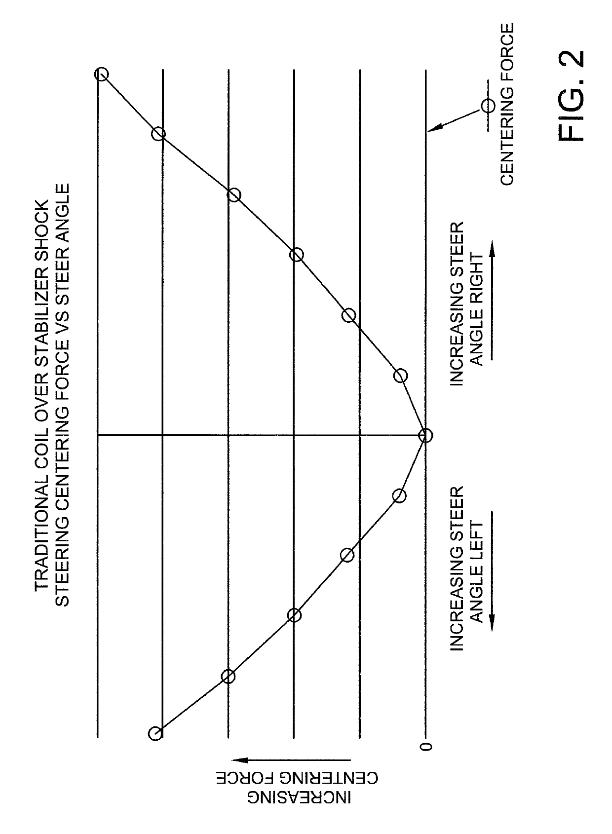
Although coil over stabilizer shocks provide adequate steering centering / damping during a vehicle turn, when the steerable axle / suspension system is near a straight alignment or zero steer angle, the centering forces imparted by the coil over springs of the stabilizer shocks on the driver side and curb side steering assembly of the axle / suspension system are very low due to the spring design.
As a result, coil over stabilizer shocks may experience some amount of wheel wobble or shimmy at the wheels attached to the auxiliary axle / suspension system near the zero turn angle due to the about zero centering force.
This can result in uneven tire wear, increased wear on the steerable axle / suspension system, and increased vehicle maintenance, as is known in the art.
Additionally, coil over stabilizer shocks are considered wear items and must be replaced at regular intervals, resulting in increased maintenance costs.
Coil over stabilizer shocks also generally exhibit steering centering forces with undesirably high intensities at increased steer angles, which can decrease tracking efficiency during turns and increase the potential of tire scrubbing of the wheels of the axle / suspension system.
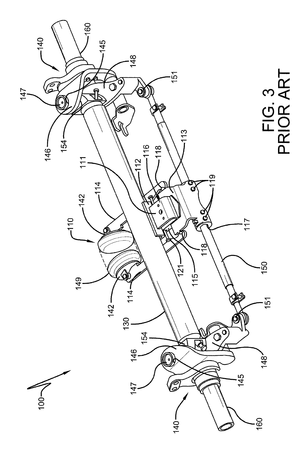
In addition, the location of the coil over stabilizer shocks can potentially have adverse effects on suspension packaging or spacing as they are relatively large and two coil over stabilizer shocks are required for each steerable axle / suspension system.
However, these pneumatic steering centering / damping mechanisms include known potential failure modes that can affect their operation, which include: loss of air pressure due to a variety of component failures, wear of the air spring, and introduction of water, ice or other contaminants into the system thereby affecting performance.
Additionally, the packaging of the air spring and its associated bracketry is quite large and can potentially limit its use to only trailer applications, where space is more available.
In truck applications, where the steering centering / damping mechanism must accommodate the vehicle drive shaft, such pneumatic steering centering / damping mechanisms generally cannot be used.
The combination of decreased wheel wobble and decreased tire scrubbing increases tire life and decreases vehicle maintenance costs.

Method used


Image

  • Steering centering/damping mechanism for a steerable heavy-duty vehicle axle/suspension system
  • Steering centering/damping mechanism for a steerable heavy-duty vehicle axle/suspension system
  • Steering centering/damping mechanism for a steerable heavy-duty vehicle axle/suspension system

Examples


Embodiment Construction

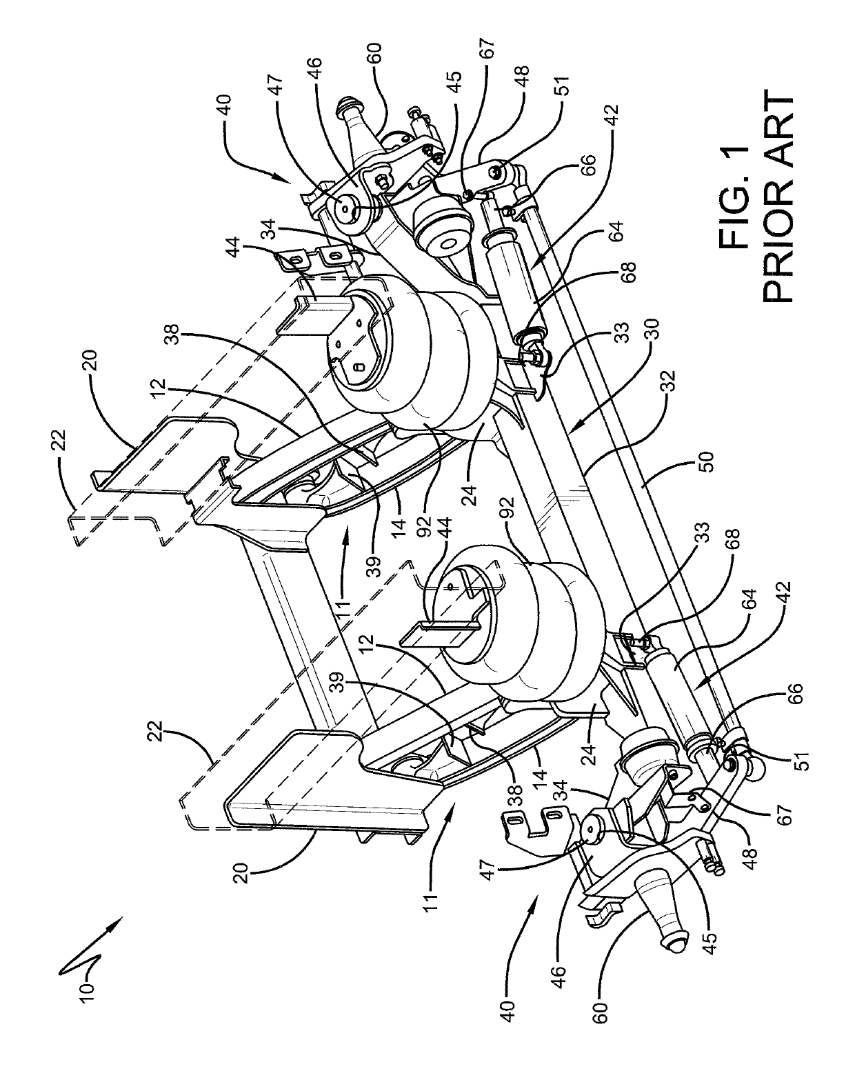
[0032]In order to better understand the steering centering / damping mechanism of the present invention and the environment in which it operates, an auxiliary steerable axle / suspension system, indicated generally at 10, incorporating a pair of prior art coil over stabilizer shocks 42, is shown in FIG. 1, and will now be described in detail below.

[0033]With continued reference to FIG. 1, auxiliary steerable axle / suspension system 10 is a self-steering auxiliary lift-axle type suspension system having a parallelogram, trailing arm geometry. Steerable axle / suspension system 10 typically is a relatively lightweight suspension, designed to permit compliance with any applicable bridge weight and stress regulations, such as the Federal Bridge Formula associated with the relevant laws and regulations applicable within the United States of America.

[0034]With continued reference to FIG. 1, steerable axle / suspension system 10 includes a pair of lift assemblies 11, a pair of hangers 20, a pair of...


PUM


Abstract

A steering centering / damping mechanism for a steerable heavy-duty vehicle axle / suspension system which includes a mechanically operated structure that provides a positive steering centering force to the axle / suspension system at a zero steer angle. The mechanically operated structure of the steering centering / damping mechanism also provides a positive steering centering force that increases in intensity as the steer angle of the axle / suspension system increases. In an embodiment of the steering centering / damping mechanism, the mechanically operated structure is a flat spring integrated into one or more steering assemblies of the axle / suspension system. The flat spring is in a pre-loaded condition at a zero steer angle to provide the positive steering centering force to the axle / suspension system at the zero steer angle, and is increasingly elastically deformed with increasing steer angles to provide the positive steering centering force which increases in intensity as the steer angle of the axle / suspension system increases.

Description

CROSS-REFERENCE TO RELATED APPLICATION[0001]This application claims the benefit of U.S. Provisional Patent Application Ser. No. 62 / 403,863, filed Oct. 4, 2016.BACKGROUND OF THE INVENTION[0002]Technical Field[0003]The invention relates generally to the art of heavy-duty vehicles. More particularly, the invention is directed to a steerable axle / suspension system for a heavy-duty vehicle. More specifically, the invention is directed to a steering centering / damping mechanism for a steerable axle / suspension system for a heavy-duty vehicle, which includes a mechanical steering centering / damping mechanism that provides a positive steering centering force at a zero steer angle to reduce wheel wobble at zero steer angle. The mechanical steering centering / damping mechanism also provides a steering centering force that increases with increasing steer angle, but with less force intensity at higher steer angles than prior art mechanical steering centering / damping mechanisms to decrease wheel sli...

Claims


Application Information

Patent Timeline
Patent Type & Authority Patents(United States)
IPC IPC(8): B62D7/22
CPCB62D7/228B60G2300/026B60G2500/40B62D7/144B60G2200/314B60G2200/445B60G2204/41B60G2206/50
Inventor WESTNEDGE, ANDREW J.GUNTERMANN, JAMES A.
Owner HENDRICKSON USA L L C
Learn More