Supercharge Your Innovation With Domain-Expert AI Agents!

Structure of a lighting display device

a technology of lighting display device and structure, which is applied in the direction of lighting device details, electric lighting, lighting and heating apparatus, etc., can solve the problems of wasting space and prime cost, and achieve the effect of reducing prime cost, convenient replacement for users, and small space needed for the transparent bottle to slant for disengagemen

Active Publication Date: 2019-11-12
HO SU FANG
View PDF1 Cites 0 Cited by
  • Summary
  • Abstract
  • Description
  • Claims
  • Application Information

AI Technical Summary

Benefits of technology

The solution enables convenient and safe replacement of the transparent bottle and bulb, reduces manufacturing costs by eliminating space and height constraints, and enhances the stability of the device during use.

Problems solved by technology

Such restriction results in a waste in space and prime cost as well.

Method used


Image

  • Structure of a lighting display device
  • Structure of a lighting display device
  • Structure of a lighting display device

Examples


Embodiment Construction

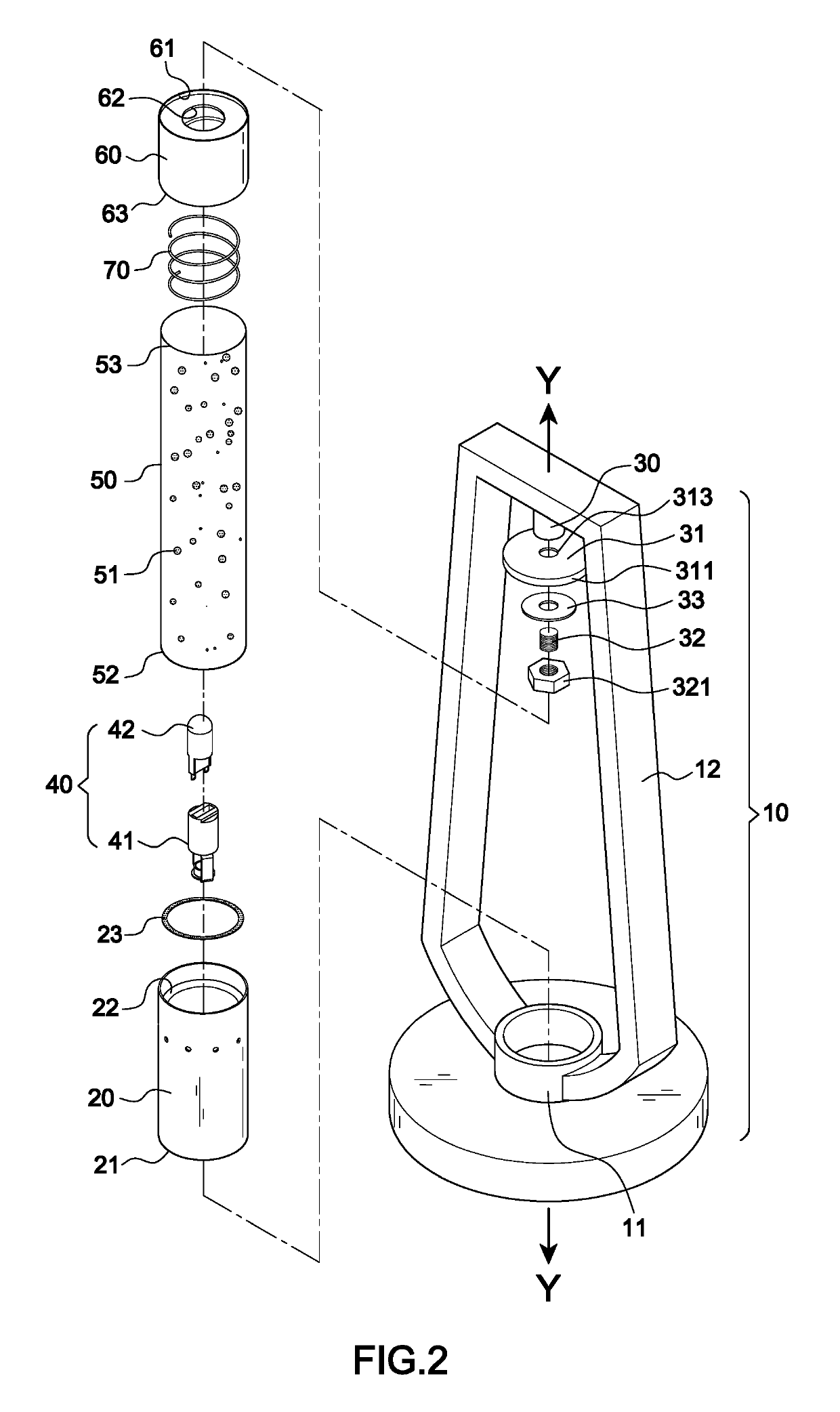
[0030]A preferred embodiment of the present invention is illustrated in FIGS. 2-8. In the embodiment, the present invention mainly comprises a frame body 10, a projection device 40, a transparent bottle 50, an assembling element 60, and a spring 70.

[0031]The frame body 10 includes a base 11 arranged at a bottom thereof, an upper fixing element 30 arranged at an upper section thereof, a stand 12, and a lower fixing element 20 arranged at a lower section thereof. The upper fixing element 30 has a positioning plate 31 arranged below which includes a peripheral wall 311 extending downwards to form a depression surface 361 and has an engaging section 32 fixed at a center thereof. The stand 12 connects the base 11 with a lower end thereof and connects the upper fixing element 30 with an upper end thereof for the upper fixing element 30 to be disposed along an axis Y-Y perpendicular to a center of the base 11. The lower fixing element 20 is fixed on the base 11, defining a lower engaging s...


PUM


Abstract

An improved structure of a lighting display device includes a lower fixing element, an upper fixing element, a projection device, a transparent bottle, and an assembling element. The projection device is disposed inside the lower fixing element and the transparent bottle is disposed thereon and fixed by a positioning annulus on an inner surface of the lower fixing element. The assembling element has an upper engaging space to be mounted on the transparent bottle and a top surface for a depression surface under a positioning plate of the upper fixing element to be engaged and fixed thereon. A spring is further disposed between the upper engaging space and the transparent bottle. Thereby the transparent bottle is able to display attractive visual effects by lighting projection and to be easily engaged and disengaged.

Description

[0001]This patent application is a continuation-in-part of Ser. No. 15 / 180,400 filed on Jun. 13, 2016.BACKGROUND OF THE INVENTION1. Field of the Invention[0002]The present invention relates to an improved structure of a lighting display device, particularly to one that displays attractive visual effects by lighting projection and one that has a structure for easy engagement and disengagement.2. Description of the Related Art[0003]Lava lamps have been common lighting fixtures in bedrooms since 1960s. In some countries they are even embedded in the mainstream cultures already. As further developed, now there are liquid motion lamps and bubble lamps. A liquid motion lamp holder improvement disclosed in U.S. Pat. No. 9,091,405 is illustrated in FIGS. 1A and 1B. The invention mainly includes base 111, a first mounted seat 112 with a first contacting room 1121, a second mounted seat 113 with a second contacting room 1131, a support bracket 114 linking the first and second mounted seats 11...

Claims


Application Information

Patent Timeline
Patent Type & Authority Patents(United States)
IPC IPC(8): F21S10/00F21V19/00F21V19/04F21S6/00F21Y115/10
CPCF21V19/00F21V19/04F21S10/002F21S6/002F21Y2115/10
Inventor HO, SU-FANG
Owner HO SU FANG
Features
  • R&D
  • Intellectual Property
  • Life Sciences
  • Materials
  • Tech Scout
  • Unparalleled Data Quality
  • Higher Quality Content
  • 60% Fewer Hallucinations
Learn More