

In-prosthesis linear drive system
a linear drive and in-prosthesis technology, applied in the direction of prosthesis, mechanical equipment, etc., can solve the problems of reducing the design flexibility of the installation of the linear drive system in the prosthesis, the inability to effectively reduce and the large dimension of the prosthesis, so as to minimize the occupation of the internal space of the prosthesis and increase the prosthetic design flexibility
- Summary
- Abstract
- Description
- Claims
- Application Information
AI Technical Summary
Benefits of technology
Problems solved by technology
Method used
Image

Examples
first embodiment
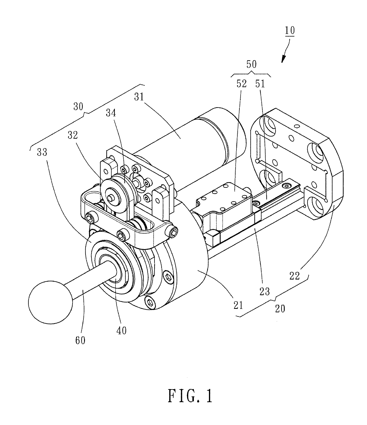
[0013]Referring to FIG. 1, an in-prosthesis linear drive system 10 in accordance with the present invention is shown. The in-prosthesis linear drive system 10 comprises a holder frame 20, a power drive 30, a screw nut 40, a screw rod limiter 50 and a screw rod 60.
[0014]The holder frame 20 comprises a first end block 21, a second end block 22, and a connection bar 23 connected between the first end block 21 and the second end block 22.
[0015]The power drive 30 comprises a motor 31, a first belt wheel 32, a second belt wheel 33 and a transmission belt 34. The motor 31 is mounted at the outer perimeter of the first end block 21 of the holder frame 20 for providing a driving force. The first belt wheel 32 is rotatably mounted at the outer perimeter of the first end block 21 of the holder frame 20 and connected to the motor 31. The second belt wheel 33 is rotatably mounted at an outer end surface of the first end block 21 of the holder frame 20. The transmission belt 34 is wound around th...
third embodiment
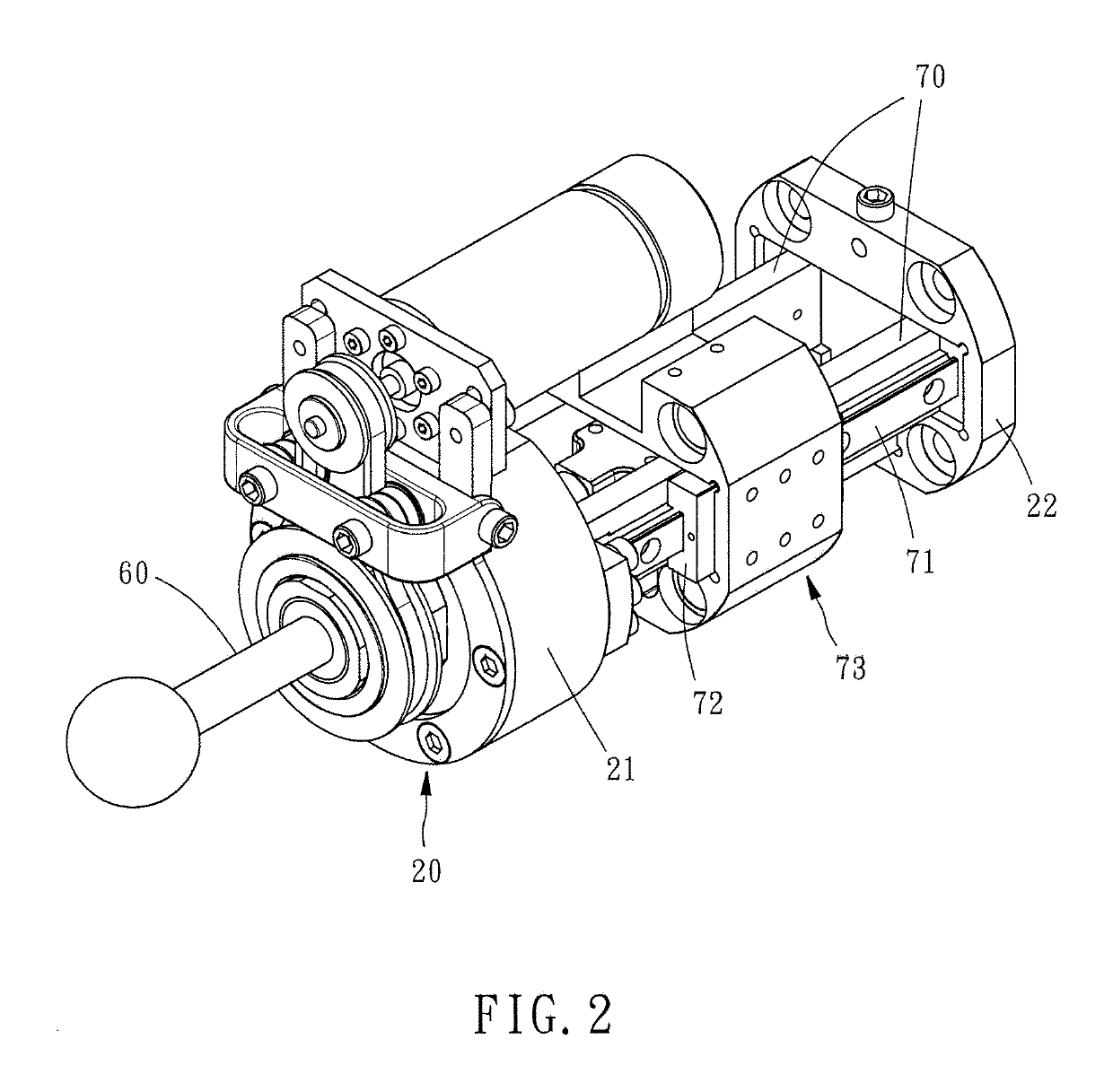
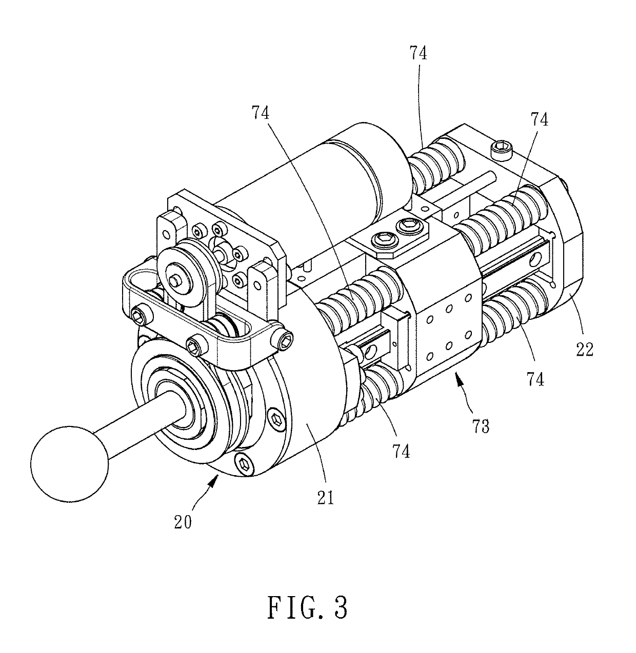
[0028]In the present invention, as illustrated in FIG. 3 and FIG. 4, the holder frame 20 further comprises four spring supporting rod members 24 respectively inserted through four corners of the adapter 72 and connected between the first end block 21 and the second end block 22 of the holder frame 20, and a plurality of buffer springs 74 respectively sleeved onto the spring supporting rod members 24 and respectively stopped between the first end block 21 and the adapter 72 and between the second end block 22 and the adapter 72. Thus, during displacement of the adapter 73, the buffer springs 74 provide a buffering effect, enhancing the operation stability of the adapter 73. Further, the adapter 73 can be worked with a position sensor 75. During displacement of the adapter 73, the position sensor 75 instantly detects the position of the adapter 73 so that an appropriate adjustment can be done according to the result of the detection.
[0029]In conclusion, the invention uses the screw nu...
PUM
 Abstract
Description
Claims
Application Information