In-prosthesis linear drive system

a linear drive and in-prosthesis technology, applied in the direction of prosthesis, mechanical equipment, etc., can solve the problems of reducing the design flexibility of the installation of the linear drive system in the prosthesis, the inability to effectively reduce and the large dimension of the prosthesis, so as to minimize the occupation of the internal space of the prosthesis and increase the prosthetic design flexibility

Active Publication Date: 2018-05-03
HIWIN TECH
View PDF13 Cites 2 Cited by
  • Summary
  • Abstract
  • Description
  • Claims
  • Application Information

AI Technical Summary

Benefits of technology

[0004]The present invention has been accomplished under the circumstances in view. It is the main object of the present invention to provide an in-prosthesis linear drive system, which increases the prosthetic design flexibility and minimizes the occupation of the prosthesis internal space.
[0006]Thus, the in-prosthesis linear drive system of the present invention uses the screw nut to drive the screw rod, causing the screw rod and the connected component to move axially back and forth along the axial direction of the screw rod. Thus, the screw nut can be selectively mounted at any location on the screw rod without limitation and, the power drive needs not to dodge the screw nut, minimizing the occupation of the prosthesis internal space.
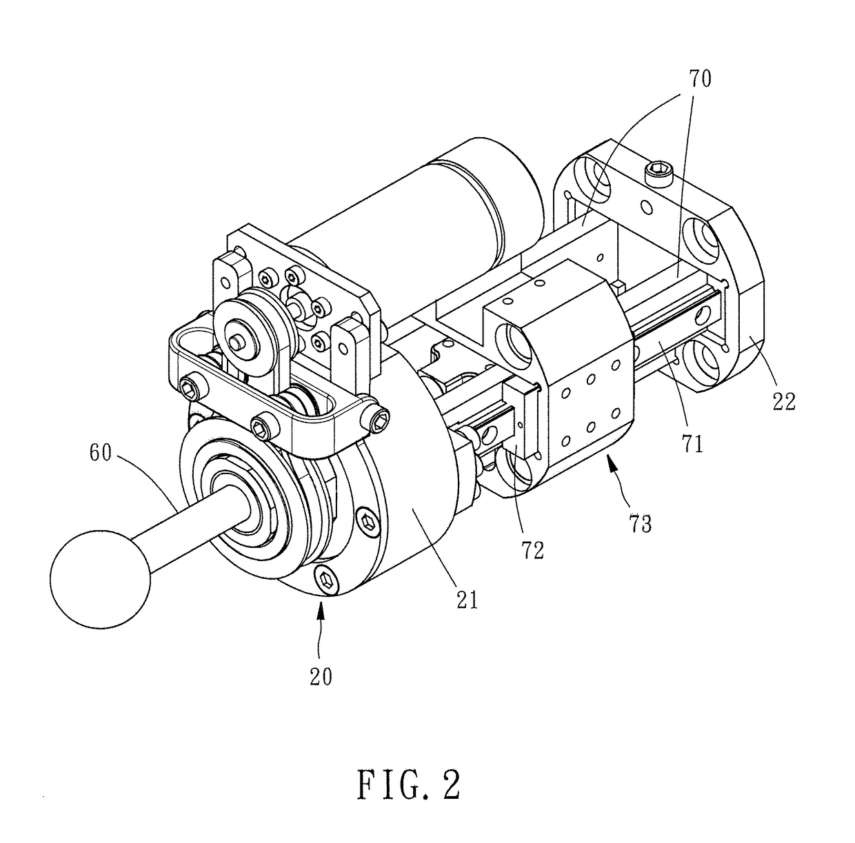
[0007]Preferably, the in-prosthesis linear drive system further comprises a rail mount, a transmission sliding guide rail, a transmission sliding block and an adapter. The rail mount is mounted on the holder frame. The transmission sliding guide rail is mounted on the rail mount and disposed at one lateral side relative to the center sliding guide rail of the screw rod limiter. Further, the transmission sliding guide rail extends in a parallel manner relative to the extending direction of the center sliding rail of the screw rod limiter. The transmission sliding block is mounted on and slidable along the transmission sliding guide rail. The adapter is mounted on the transmission sliding block and connected to the center sliding block of the screw rod limiter for synchronous displacement with the screw rod. Thus, the in-prosthesis linear drive system can use the adapter for the connection of other components under different installation methods, provide a buffering force to the operation of the adapter by means of a buffer spring, and instantly detect the position of the adapter using a position sensor.

Problems solved by technology

The method of using a power drive to rotate a screw rod in moving a screw nut limits the installation of the power drive to the area around the two opposite ends of the screw rod, reducing the design flexibility of the installation of the linear drive system in the prosthesis.
More particularly, when considering the stroke of the screw nut, the power drive must leave a space for enabling the screw nut to move unimpeded.
Thus, the installation space in the prosthesis for the linear drive system cannot be effectively reduced, resulting in a large dimension of the prosthesis.
Thus, the width of the internal space of the prosthesis must be greater than the combined width of the screw rod and the screw nut, causing the internal space of the prosthesis unable to be effectively reduced.

Method used


Image

  • In-prosthesis linear drive system
  • In-prosthesis linear drive system
  • In-prosthesis linear drive system

Examples


first embodiment

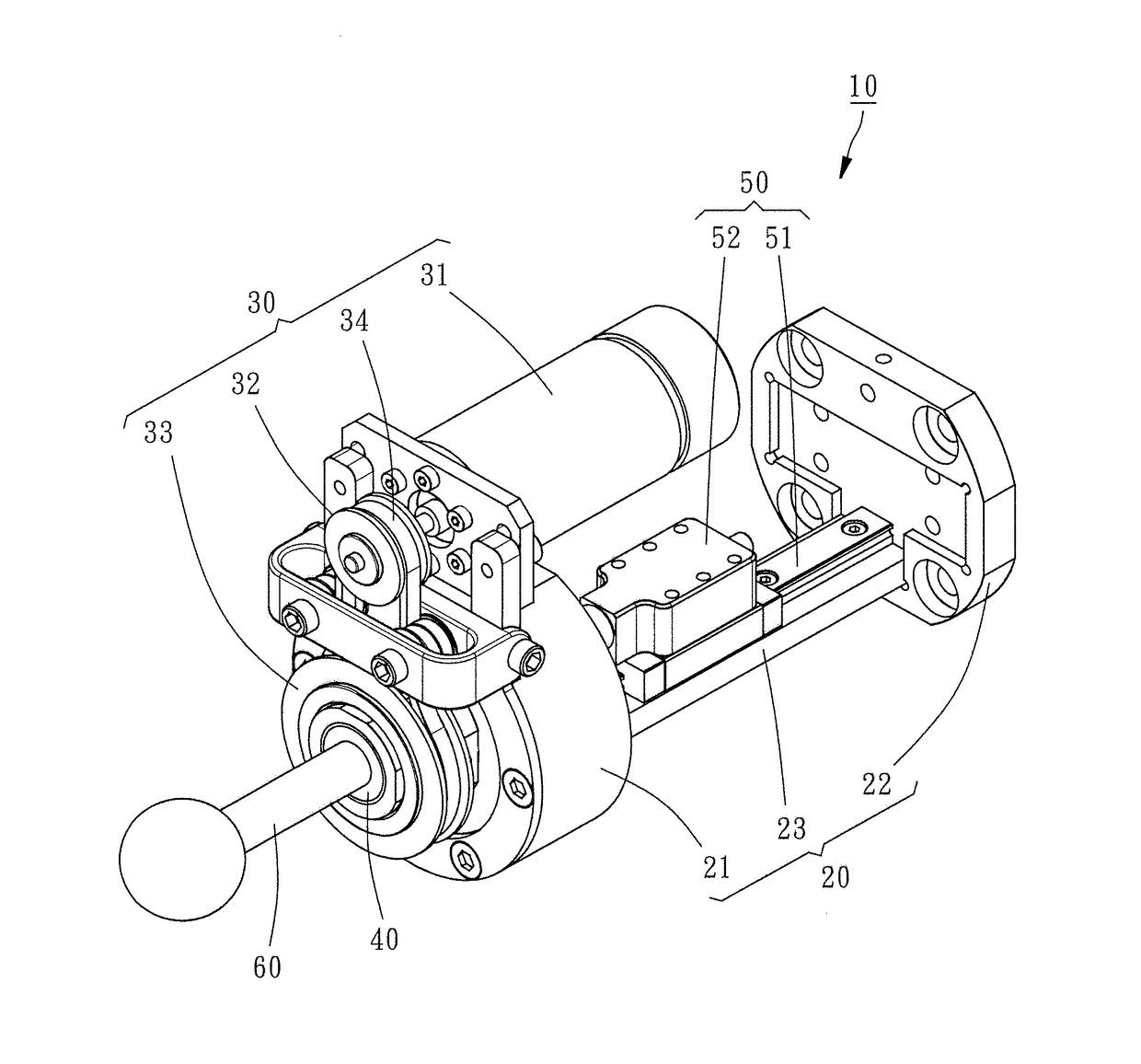
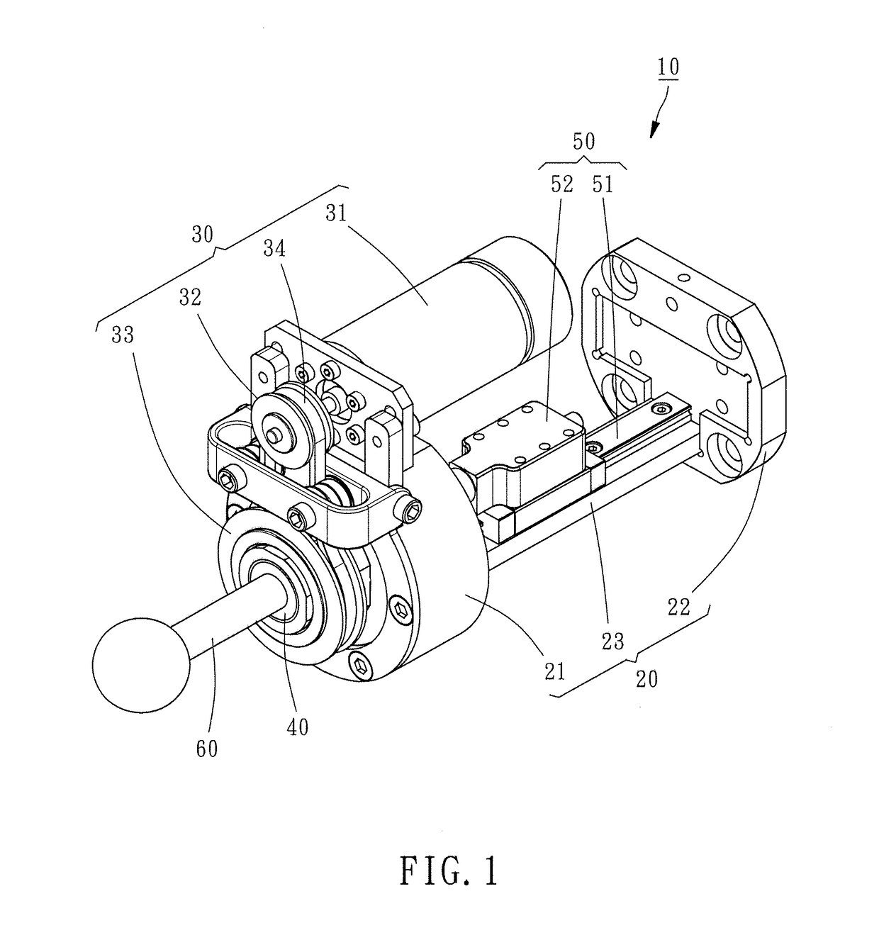
[0013]Referring to FIG. 1, an in-prosthesis linear drive system 10 in accordance with the present invention is shown. The in-prosthesis linear drive system 10 comprises a holder frame 20, a power drive 30, a screw nut 40, a screw rod limiter 50 and a screw rod 60.

[0014]The holder frame 20 comprises a first end block 21, a second end block 22, and a connection bar 23 connected between the first end block 21 and the second end block 22.

[0015]The power drive 30 comprises a motor 31, a first belt wheel 32, a second belt wheel 33 and a transmission belt 34. The motor 31 is mounted at the outer perimeter of the first end block 21 of the holder frame 20 for providing a driving force. The first belt wheel 32 is rotatably mounted at the outer perimeter of the first end block 21 of the holder frame 20 and connected to the motor 31. The second belt wheel 33 is rotatably mounted at an outer end surface of the first end block 21 of the holder frame 20. The transmission belt 34 is wound around th...

third embodiment

[0027]In the present invention, as illustrated in FIG. 3 and FIG. 4, the holder frame 20 further comprises four spring supporting rod members 24 respectively inserted through four corners of the adapter 72 and connected between the first end block 21 and the second end block 22 of the holder frame 20, and a plurality of buffer springs 74 respectively sleeved onto the spring supporting rod members 24 and respectively stopped between the first end block 21 and the adapter 72 and between the second end block 22 and the adapter 72. Thus, during displacement of the adapter 73, the buffer springs 74 provide a buffering effect, enhancing the operation stability of the adapter 73. Further, the adapter 73 can be worked with a position sensor 75. During displacement of the adapter 73, the position sensor 75 instantly detects the position of the adapter 73 so that an appropriate adjustment can be done according to the result of the detection.

[0028]In conclusion, the invention uses the screw nu...


PUM


Abstract

An in-prosthesis linear drive system includes a holder frame, a power drive mounted on the holder frame, a screw nut mounted on the holder frame and coupled to the power drive and rotatable on the axis thereof by the power drive, a screw rod limiter including a center sliding guide rail mounted on the holder frame and a center sliding block slidable along the center sliding guide rail, and a screw rod threaded into the screw nut and connected with the center sliding block of the screw rod limiter and movable along the axial direction of the screw nut upon rotation of the screw nut. Thus, using the screw nut to drive the screw rod achieves the effect of minimizing the occupation of the prosthesis internal space.

Description

BACKGROUND OF THE INVENTION1. Field of the Invention[0001]The present invention relates to linear driving technology and more particularly, to an in-prosthesis linear drive system that minimizes the occupation of the prosthesis internal space.2. Description of the Related Art[0002]In a linear drive system for prosthetic applications, for example, ball screw, a power drive, such as motor or speed reducer, is generally used for rotating a screw rod to cause forward or backward displacement of a screw nut along the screw rod, so that the screw nut can carry an attached structure forward or backward. The method of using a power drive to rotate a screw rod in moving a screw nut limits the installation of the power drive to the area around the two opposite ends of the screw rod, reducing the design flexibility of the installation of the linear drive system in the prosthesis. More particularly, when considering the stroke of the screw nut, the power drive must leave a space for enabling th...

Claims


Application Information

Patent Timeline
Patent Type & Authority Applications(United States)
IPC IPC(8): H02K7/06H02K7/14
CPCH02K7/06A61F2/68H02K7/14F16H25/2015F16H25/2018F16H37/00F16H2025/2037F16H2025/204F16H2025/2096A61F2/70H02K7/116A61F2/64F16H25/20
Inventor WANG, REN-JENG
Owner HIWIN TECH
Why Eureka
Try Eureka