
Stereoscopic video encoding/decoding apparatuses supporting multi-display modes and methods thereof

a video encoding and video technology, applied in the field of stereoscopic video encoding/decoding apparatus, can solve the problems of increased image restoration amount in the decoding apparatus, decreased transmission efficiency, and increased decoding time delay, so as to reduce the overall display delay, simplify the decoding process, and enhance transmission efficiency

Inactive Publication Date: 2011-10-27
ELECTRONICS & TELECOMM RES INST
View PDF5 Cites 7 Cited by
  • Summary
  • Abstract
  • Description
  • Claims
  • Application Information

AI Technical Summary

Benefits of technology

The present invention is a stereoscopic video encoding and decoding apparatus that supports multi-display modes. It uses motion and disparity compensation to efficiently transmit only essential data and reduce the amount of data transmitted over the network. The apparatus separates right and left-eye input images and encodes them separately, allowing for easy selection of display modes. The decoding apparatus can restore an image in a requested display mode even if there is only one layer of data available. The technical effects of the invention include improved video quality, reduced data usage, and improved user experience.

Problems solved by technology

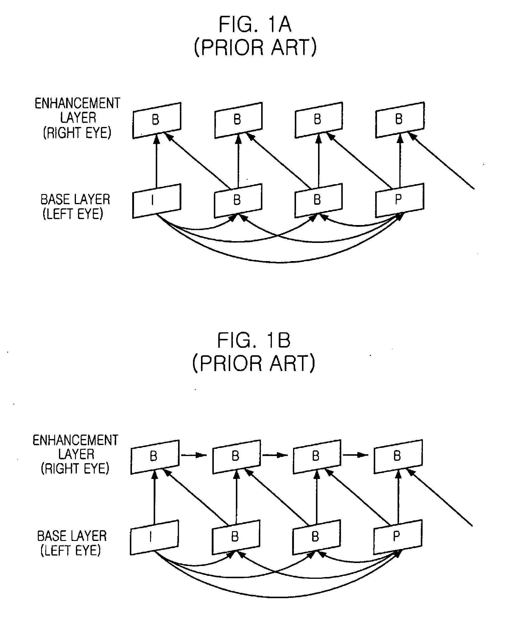
If the display mode of the reception end is a three-dimensional video field shuttering display, which is commonly adopted in most personal computers at present, there is a problem that inessential even-numbered field information of the left-eye image and odd-numbered field information of the right-eye image should be transmitted together so as for the reception end to restore a needed image.
Therefore, there are serious problems that transmission efficiency is decreased, and the amount of image restoration in the decoding apparatus and the decoding time delay are increased.
However, there are problems, too.
Therefore, it is not suitable for a frame shuttering display mode where right and left-eye images are displayed simultaneously.

Method used


Image

  • Stereoscopic video encoding/decoding apparatuses supporting multi-display modes and methods thereof
  • Stereoscopic video encoding/decoding apparatuses supporting multi-display modes and methods thereof
  • Stereoscopic video encoding/decoding apparatuses supporting multi-display modes and methods thereof

Examples


Embodiment Construction

[0050]Other objects and aspects of the invention will become apparent from the following description of the embodiments with reference to the accompanying drawings, which is set forth hereinafter.

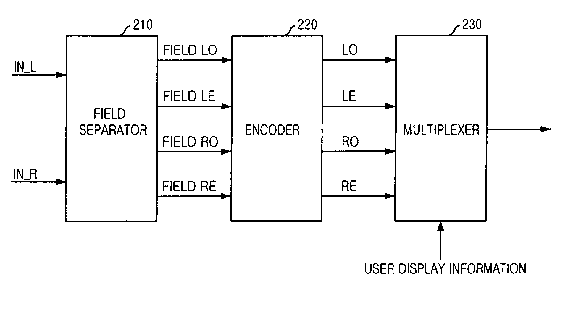
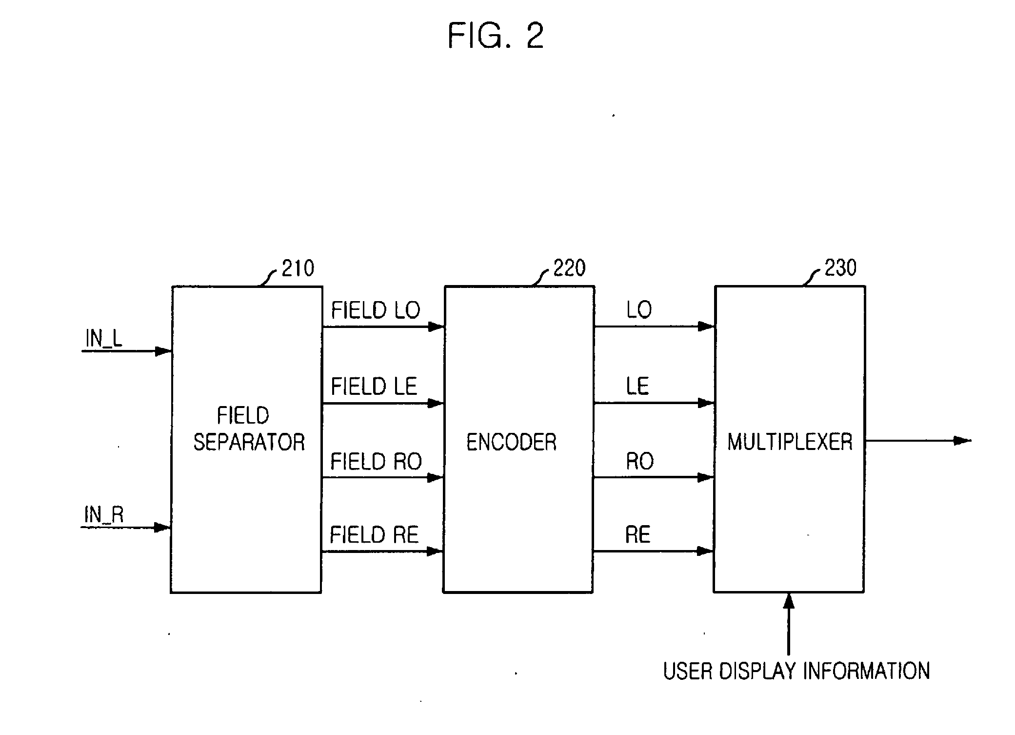
[0051]FIG. 2 shows a structural diagram describing a stereoscopic video encoding apparatus that supports multi-display modes in accordance with an embodiment of the present invention. As illustrated in the drawing, the encoding apparatus of the present invention includes a field separator 210, an encoder 220, and a multiplexer 230.

[0052]The field separator 210 performs the function of separating two-channel right and left-eye images into odd-numbered fields and even-numbered fields, and converting them into four-channel input images.

[0053]FIG. 3 shows an exemplary diagram of a field separator separating an image into odd and even fields in the right and left-eye images, respectively. As shown in the drawing, the field separator 210 of the present invention separates a one-frame image for th...


PUM


Abstract

Provided is a stereoscopic video encoding and / or decoding apparatus that supports multi-display modes, the encoding / decoding method thereof and computer-readable recording medium for recording a program that implements the encoding / decoding method. The encoding apparatus of this research incorporates: a field separating means for separating right and left-eye input images into an odd field of the left-eye image (LO), even field of the left-eye image (LE), odd-numbered field (RO) of the right-eye image, and even-numbered field (RE) of the right-eye image; an encoding means for encoding the fields separated in the field separating means by performing motion and disparity compensation; and a multiplexing means for multiplexing the essential fields among the fields received from the encoding means, based on the user display information.

Description

TECHNICAL FIELD[0001]The present invention relates to a stereoscopic video encoding / decoding apparatus that supports multi-display modes, encoding and / or decoding method thereof, and a computer-readable recording medium for recording a program that implements the method; and, more particularly, to a stereoscopic video encoding / decoding apparatus that supports multi-display modes that make it possible to perform decoding with essential encoding bit stream only needed for a selected stereoscopic display mode, so as to transmit video data efficiently in an environment where a user can select a display mode, encoding and / or decoding method thereof, and a computer-readable recording medium for recording a program to implement the methodsBACKGROUND ART[0002]Generally, in case of a two-dimensional video image, one-eye images exist on a time axis, whereas in case of a three-dimensional image, two or more-eye images exist on the same time axis. Moving Picture Experts Group-2-Multiview Profil...

Claims


Application Information

Patent Timeline
Patent Type & Authority Applications(United States)
IPC IPC(8): H04N11/04H04N7/58H04N13/00H04N15/00H04N21/2343H04N21/258H04N21/4402
CPCH04N13/0048H04N13/0055H04N13/0285H04N13/0438H04N13/0456H04N19/597H04N21/25825H04N21/440227H04N21/44029H04N2013/0081H04N2013/0085H04N21/234327H04N13/341H04N13/189H04N13/161H04N13/286H04N13/361H04N21/2365H04N21/434
Inventor CHOI, YUNJUNGCHO, SUK-HEEYUN, KUG-JINLEE, JINHWANAHN, CHIETEUK
Owner ELECTRONICS & TELECOMM RES INST
Learn More