
High power factor converter

Active Publication Date: 2019-11-12
NAT CHUNG SHAN INST SCI & TECH
View PDF6 Cites 0 Cited by
  • Summary
  • Abstract
  • Description
  • Claims
  • Application Information

AI Technical Summary

Benefits of technology

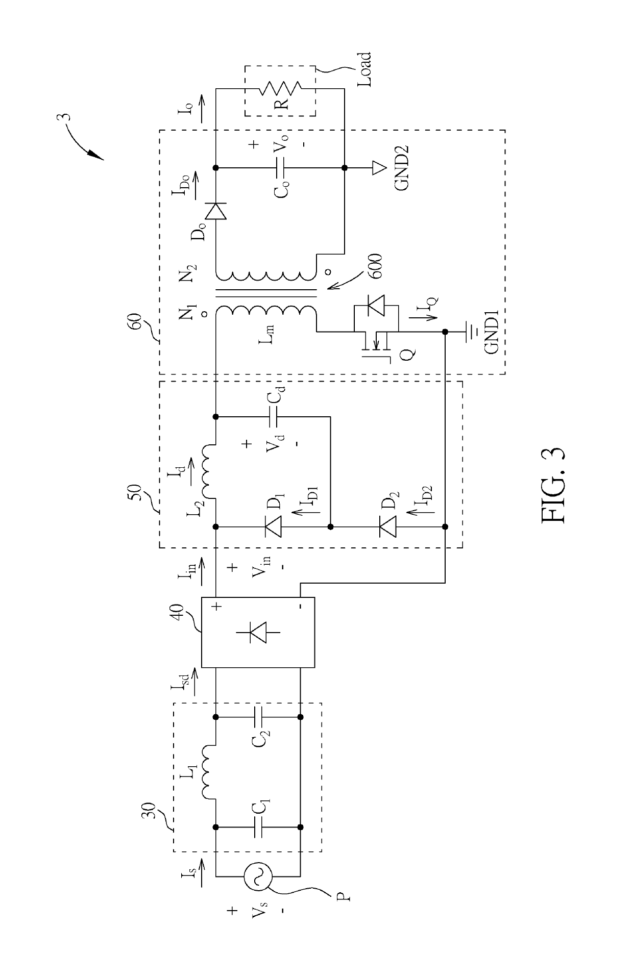
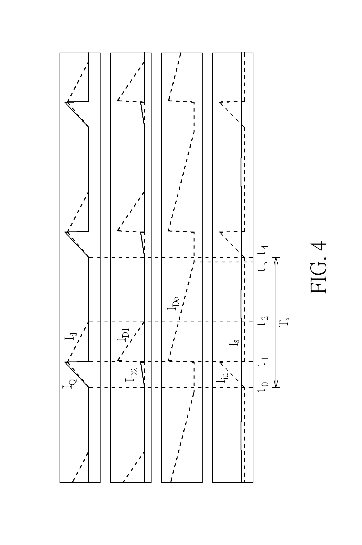
[0020]According to one embodiment of the present invention, when the input DC voltage is smaller than or equal to a voltage across the reactive power control capacitor and the switch is turned on, the reactive power control capacitor, the transformer, the switch and the second diode form a converter transformer magnetization path, such that the transformer stores the energy based on the magnetizing inductance of the transformer.
[0021]According to one embodiment of the present invention, when the input DC voltage is smaller than or equal to a voltage ac

Problems solved by technology

According to equation (3), if a lower secondary ripple of the output voltage is required and the mains frequency ω is usually quite low, a large output capacitor is needed, resulting in practically difficult in practical applications.

Method used


Image

  • High power factor converter
  • High power factor converter
  • High power factor converter

Examples


Embodiment Construction

[0032]The following illustrates specific embodiments of the present invention, and those skilled in the art can readily understand advantages and efficacy of the present invention accordingly.

[0033]Certain terms are used throughout the description and following claims to refer to particular components. As one skilled in the art will appreciate, hardware manufacturers may refer to a component by different names. This document does not intend to distinguish between components that differ in name but not function. In the following description and in the claims, the terms “include” and “comprise” are utilized in an open-ended fashion, and thus should be interpreted to mean “include, but not limited to . . . ”. Also, the term “couple” is intended to mean either an indirect or direct electrical connection. Accordingly, if one device is coupled to another device, that connection may be through a direct electrical connection, or through an indirect electrical connection via other devices an...


PUM


Abstract

A high power factor converter is provided. The high power factor converter includes a rectifier, a reactive power control circuit and a converter circuit. The rectifier is utilized for receiving and converting an input AC voltage in to an input DC voltage. The reactive power control circuit is coupled to the rectifier for performing a reactive power control operation based on the input DC voltage. The converter circuit is coupled to the reactive power control circuit for converting the input DC voltage into an output voltage.

Description

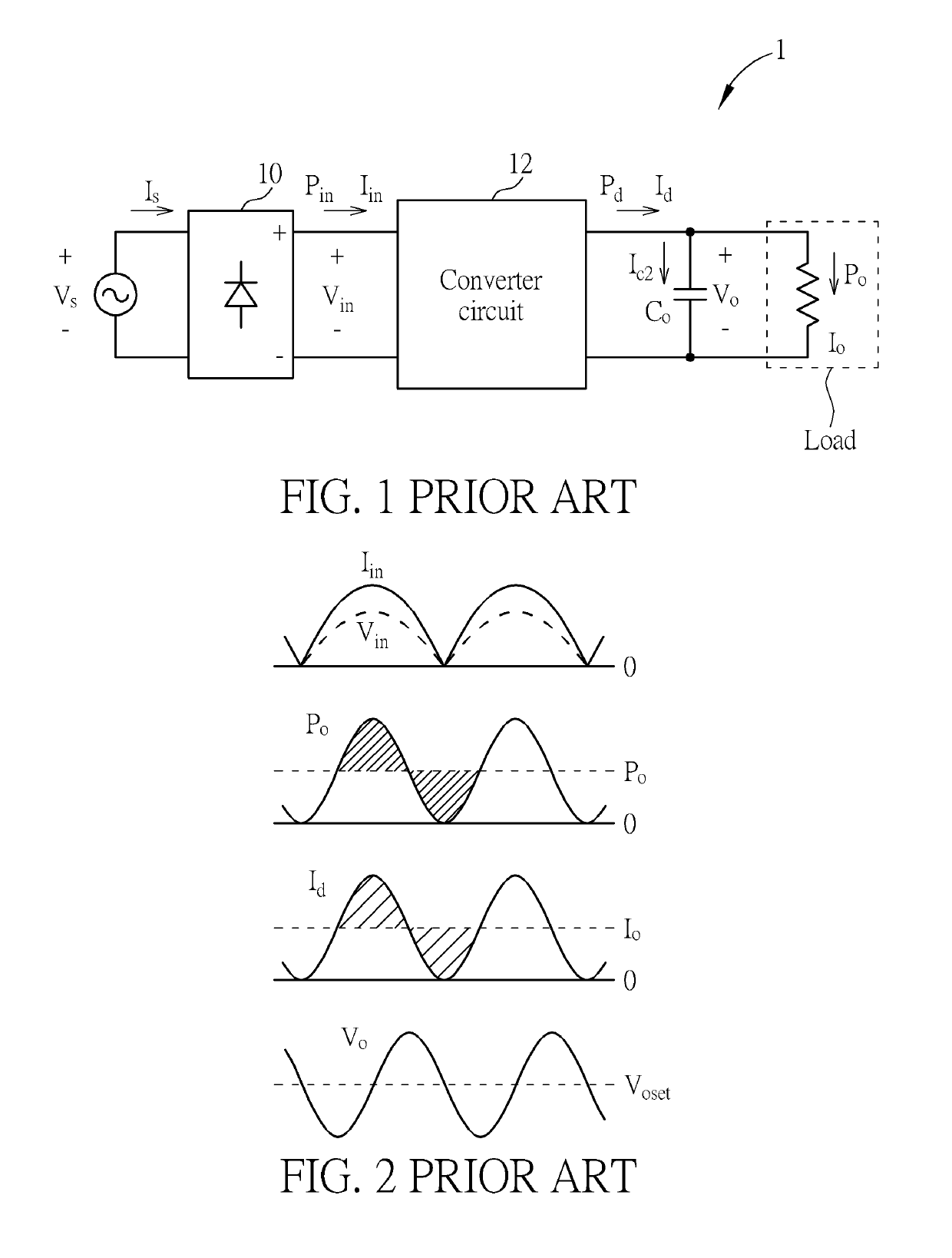
BACKGROUND OF THE INVENTION1. Field of the Invention[0001]The present invention relates to a converter, and more particularly, to a converter capable of providing high power factor and low output voltage ripple.2. Description of the Prior Art[0002]With advanced development in technology, various electronic products, such as a notebook, a mobile phone, a personal digital assistant, a multimedia player, etc., have been presented and are utilized widely in daily life. In general, a power converter is required for providing operating power for the electronic products. Furthermore, the power converter is capable of converting an alternating current (AC) power to a direct current (DC) power for operation of the electronic products.[0003]Please refer to FIG. 1 and FIG. 2. FIG. 1 is a schematic diagram of a conventional flyback converter 1 according to the prior art. FIG. 2 is a waveform diagram illustrating waveform of the conventional flyback converter 1 shown in FIG. 1 operating at unity...

Claims


Application Information

Patent Timeline
IPC IPC(8): H02M1/42H02M1/14H02M1/44H02M3/335
CPCH02M3/33507H02M1/14H02M1/4208H02M1/44H02M1/4258H02M1/4266H02M1/346Y02B70/10
Inventor CHEN, KUN-FENGWANG, JUNG-YANGHO, CHIN-YU
Owner NAT CHUNG SHAN INST SCI & TECH
Learn More