
Method and system for carrying out plasma chemical reaction in gas flow

a plasma chemical reaction and gas flow technology, applied in the field of low-current high-voltage plasmatrons, can solve the problems of loss of electron energy, gas heating, and approach not being as effective, and achieve the effect of reducing the energy loss of electrons and reducing the energy loss

Active Publication Date: 2019-11-12
DM ECO PLASMA INC
View PDF3 Cites 0 Cited by
  • Summary
  • Abstract
  • Description
  • Claims
  • Application Information

AI Technical Summary

Problems solved by technology

Regular plasma technologies, such as thermal electric arc or microwave electric discharge and non-equilibrium plasmas like DBD, or corona discharges, have some disadvantages for plasma chemical applications.
The problem is to provide optimal conditions for carrying out direct chemical reactions (chemical reactions which transmit initial reagents to the substances needed) and to prevent to the extent possible the reverse chemical reactions.
The problem with this is that all energy of the electrons, which during acceleration process goes into the heating of the gas, is lost.
At first glance, this approach appears not to be as effective as the first one, because in this case energy has to be spent for heating all the molecules, not only the ones needed for the reagent.
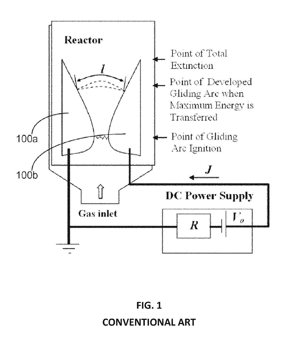
A major disadvantage of such geometry is relatively small arc filament length in comparison with the reactor's dimensions.
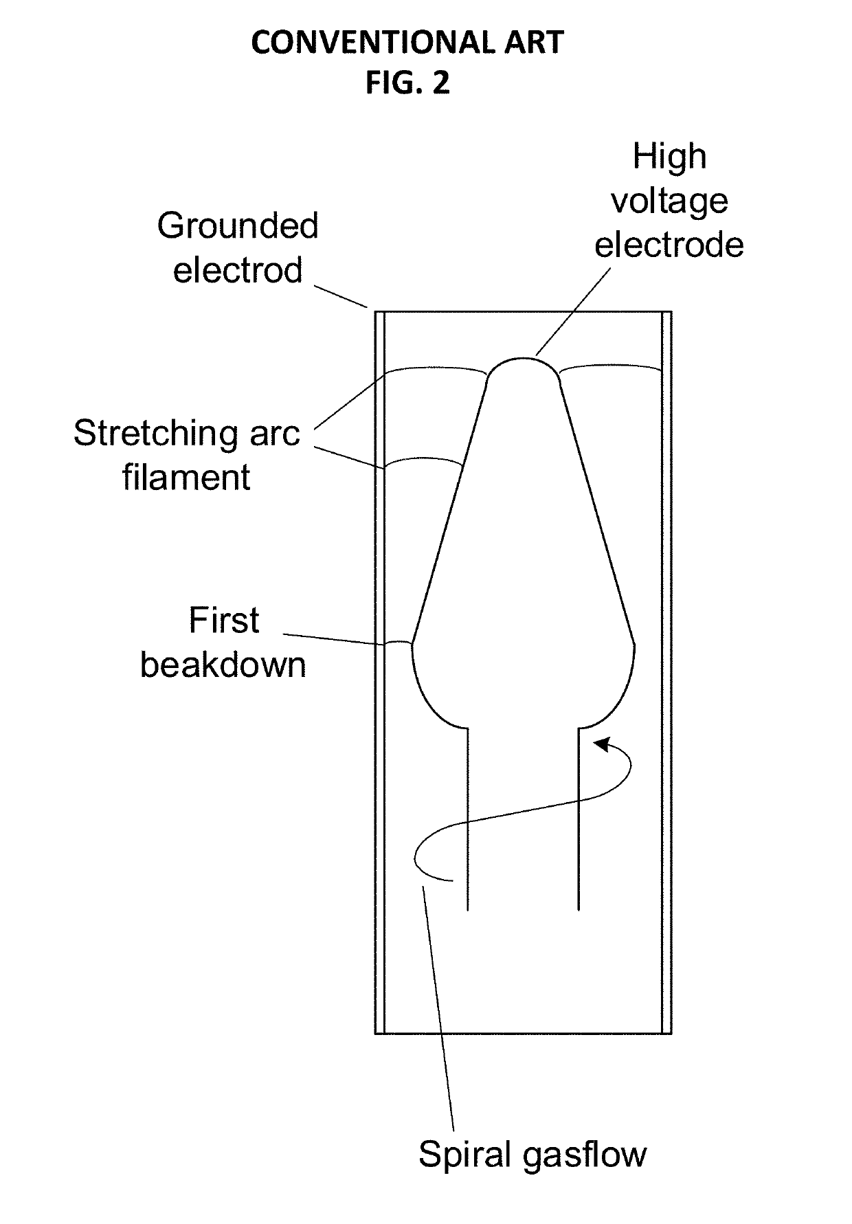
A disadvantage of gliding arc in reverse vortex is a narrow region of changing plasma parameters achievable in this kind of discharge.
The region of gas velocities which can provide conditions for the revers vortex creation and the corresponding gliding arc discharge form are limited and create limitations for plasma parameters region.
Another limitation of this kind of discharge is the limitation on gas velocity in the discharge chamber.
It cannot be higher than several meters per second, because of the discharge chamber geometry and because of the arc breakup.

Method used


Image

  • Method and system for carrying out plasma chemical reaction in gas flow
  • Method and system for carrying out plasma chemical reaction in gas flow
  • Method and system for carrying out plasma chemical reaction in gas flow

Examples


example # 1

Example #1

[0059]Conversion of CO2 in plasma-chemical reactor based on low current high voltage plasmatron was performed. CO2 was input to the system that includes a high voltage plasmatron designed according to the above description, heat exchanger and recirculation pump. Gas goes through plasmatron, than goes through heat exchanger for cooling and then part of gas goes back to the plasmatron input and another part of gas goes to the output for gas analysis.

[0060]Parameters of Experiment:

[0061]1. Plasmatron input power: 1600 W

[0062]2. Input CO2 flow rate: 2 m3 / h

[0063]3. Recycle pump flow rate: 25 m3 / h

[0064]4. Plasmatron output channel diameter: 6 mm

[0065]Output Gas Composition:

[0066]CO: 15%

[0067]O2: 7.5%

[0068]CO2: 77.5%

example # 2

Example #2

[0069]Conversion of CO2 in plasma-chemical reactor based on low current high voltage plasmatron was performed. CO2 was input to the system that includes a high voltage plasmatron designed according to the above description, heat exchanger and recirculation pump. Gas goes through plasmatron, than goes through heat exchanger for cooling and then part of gas goes back to the plasmatron input and other part of gas goes to the output for gas analysis.

[0070]Parameters of Experiment:

[0071]1. Plasmatron input power: 1600 W

[0072]2. Input CO2 flow rate: 2 m3 / h

[0073]3. Recycle pump flow rate: 5 m3 / h

[0074]4. Plasmatron output channel diameter: 6 mm

[0075]Output Gas Composition:

[0076]CO: 11%

[0077]O2: 5.5%

[0078]CO2: 83.5%

example # 3

Example #3

[0079]Conversion of CO2 in plasma-chemical reactor based on low current high voltage plasmatron was performed. CO2 was input to the system that includes a high voltage plasmatron designed according to the above description, a heat exchanger and a recirculation pump. Gas goes through plasmatron, than goes through the heat exchanger for cooling and then part of the gas goes back to the plasmatron input and another part of gas goes to the output for gas analysis.

[0080]Parameters of Experiment:

[0081]1. Plasmatron input power: 1600 W

[0082]2. Input CO2 flow rate: 2 m3 / h

[0083]3. Recycle pump flow rate: 2 m3 / h

[0084]4. Plasmatron output channel diameter: 6 mm

[0085]Output Gas Composition:

[0086]CO: 8%

[0087]O2: 4%

[0088]CO2: 88%

[0089]As can be seen from these examples, gas flow through the plasmatron channel provided by recirculation pump is a one of the important parameters that determine gas conversion efficiency by plasma, because it determines the electric discharge mode.

[0090]Typi...


PUM


Abstract

A plasma chemical reactor including an anode having a generally cylindrical shape and an axis of rotational symmetry; a cathode inside the anode and co-axial with the anode; a hot plasma channel between the between the anode and the cathode; a gas input module providing gas flow into the anode; a gas output module at a distal end of the anode; and a high voltage power supply providing with a current in a range of 0.1-1.0 A. The high voltage power supply provides a voltage to the cathode in a range of 0-5 kV, a power of at least 1 kW, and a voltage / current ratio of at least 1000 V / A.

Description

BACKGROUND OF THE INVENTIONField of the Invention[0001]This invention relates to low current high-voltage plasmatrons and their use for stimulation of chemical reactions with a high activation barrier, plasma chemical reactors, plasma assisted combustion and laboratory purposes.Description of the Related Art[0002]Plasma is a powerful instrument for carrying out of chemical reactions with high activation energy such as, for example, syngas production, CO2 dissociation, H2S dissociation, etc. Regular plasma technologies, such as thermal electric arc or microwave electric discharge and non-equilibrium plasmas like DBD, or corona discharges, have some disadvantages for plasma chemical applications. The problem is to provide optimal conditions for carrying out direct chemical reactions (chemical reactions which transmit initial reagents to the substances needed) and to prevent to the extent possible the reverse chemical reactions. Also, the conditions providing useful recuperation of var...

Claims


Application Information

Patent Timeline
Patent Type & Authority Patents(United States)
IPC IPC(8): H05H1/34B01J12/00H05H1/00B01J19/08
CPCB01J12/002B01J19/088H05H1/3405H05H1/0081B01J2219/0809B01J2219/0875B01J2219/0869H05H2001/3442B01J2219/0824B01J2219/083H05H1/482H05H1/3442
Inventor MEDVEDEV, DMITRY
Owner DM ECO PLASMA INC
Learn More