Microfluidic Chemical Reaction Circuits

a chemical reaction circuit and microfluidic technology, applied in the direction of liquid-gas reaction process, chemical/physical/physical-chemical stationary reactor, ion-exchange treatment of water/sewage, etc., can solve the problems of inability to confine each individual step, poor overall performance, and considerable challenges in applying microfluidic technology to sequential syntheses

Inactive Publication Date: 2008-11-13
CALIFORNIA INST OF TECH +3
View PDF72 Cites 206 Cited by
  • Summary
  • Abstract
  • Description
  • Claims
  • Application Information

AI Technical Summary

Benefits of technology

[0007]In one aspect, the invention provides a method for removing a solvent system from a microfluidic reactor by (i) providing a microfluidic device comprising a reactor, where the reactor (a) is configured to fluidically communicate with at least one microfluidic channel; (b) is configured to be fluidically isolated; and (c) is defined by a wall at least a portion of which is permeable to a gas but substantially impermeable to a liquid corresponding to the gas; where the reactor optionally contains a first solvent system and, if present, the first solvent system comprises a first solute and optionally comprised additional solutes; ii) introducing into the reactor a second solvent system comprising a second solute and optionally comprised additional solutes; iii) isolating the reactor, whereby the reactor contains a third solvent system and a solute denoted Solute A, where Solute A is first solute, the second solute, or a product of a reaction in which either or both of the first and second solutes are reactants and where the third solvent system is the same as the second solvent system or is a solvent system comprised of the combination of the first and second solvent systems; iv) withdrawing at least 25% of the volume of the third solvent system from the fluidically isolated reactor, where the third solvent system is withdrawn from the reactor more rapidly than Solute A is withdrawn, and where the amount of Solute A in the reactor per unit volume of the third solvent system in the reactor increases as the third solvent system is withdrawn. In one embodiment Solute A is in solution in the third solvent system the concentration of Solute A in the reactor increases as the third solvent system is withdrawn.
[0008]In one aspect, the invention provides a method for carrying out a chemical reaction using a microfluidic device by i) providing a microfluidic device comprising a reactor, where the reactor (a) is configured to fluidically communicate with at least one microfluidic channel; (b) is configured to be fluidically isolated; and (c) is defined by a wall at least a portion of which is permeable to a gas but substantially impermeable to a liquid corresponding to the gas; ii) introducing into the reactor a first solvent system comprising a first reactant; iii) fluidically isolating the reactor and withdrawing some or all of the first solvent system from the fluidically isolated reactor while retaining the first reactant in the reactor; iv) introducing into the reactor a second solvent system comprising a second reactant, where the first reactant and the second reactant are compounds that chemically react, under reaction conditions, to generate a product. The method may include the further steps of fluidically isolating the reactor and maintaining the reactor in a fluidically isolated state for a time and under conditions sufficient for a first reaction product to accumulate in ...

Problems solved by technology

However, considerable challenges remain in applying microfluidic technology to sequential syntheses of fine chemicals and pharmaceuticals.
However, in multi-step procedures, flow-through systems are plagued by cross contamination of reagents from d...

Method used


Image

  • Microfluidic Chemical Reaction Circuits
  • Microfluidic Chemical Reaction Circuits
  • Microfluidic Chemical Reaction Circuits

Examples


example 1

Synthesis of [19F]FDG

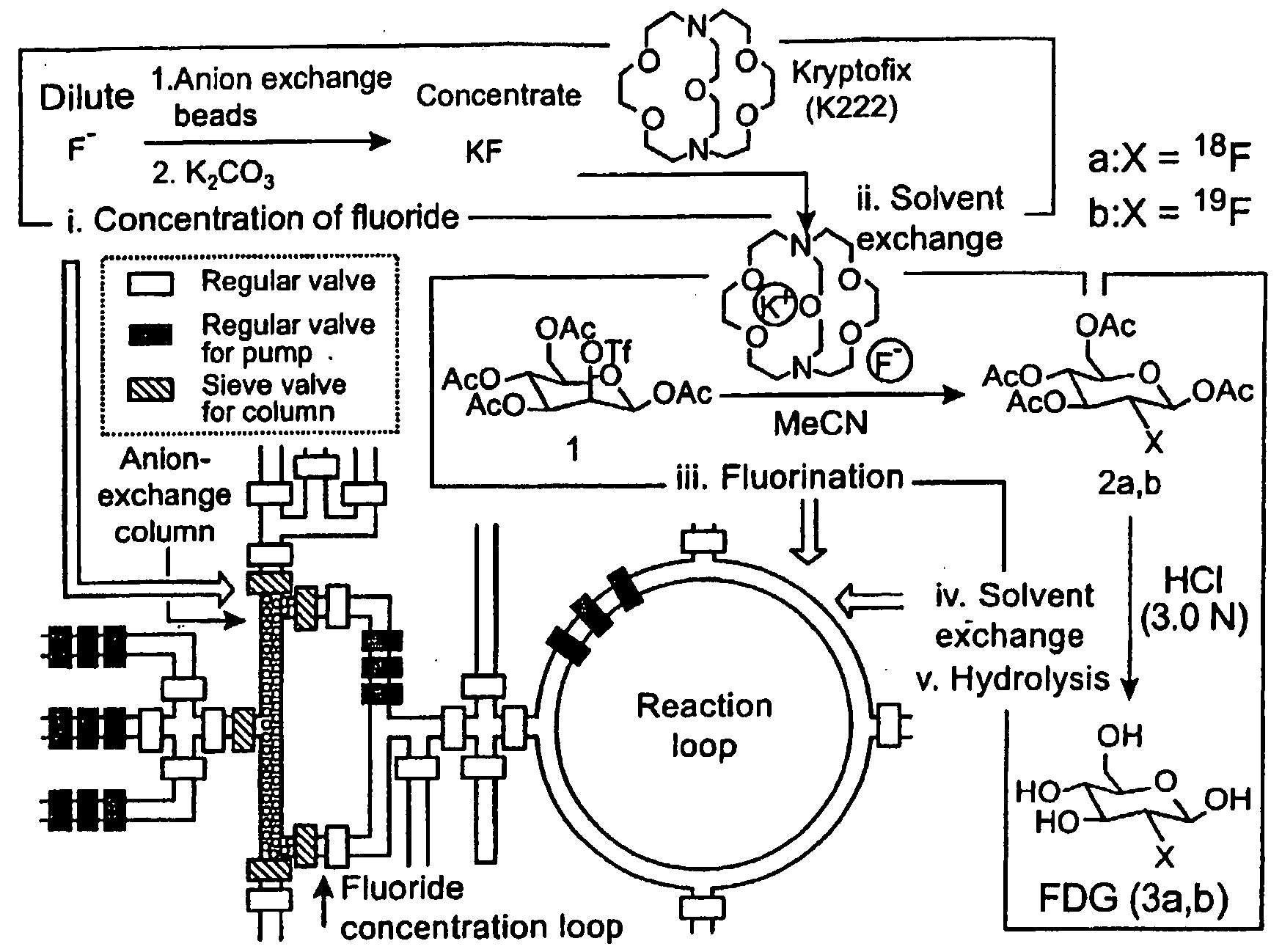
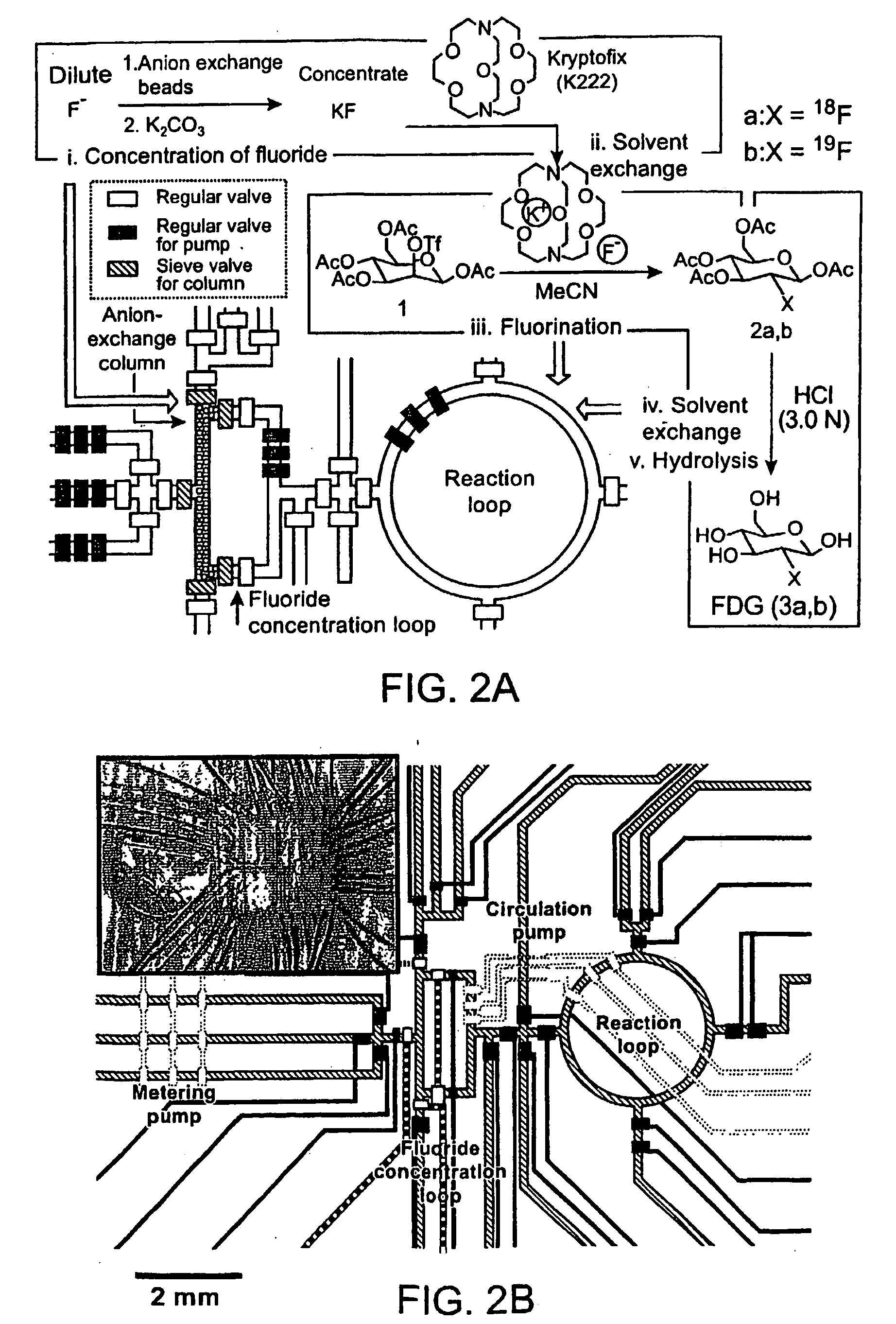
[0244]The molecular imaging probe 2-deoxy-2-[18F]fluoro-D-glucose ([18F]FDG) is a widely used radiopharmaceutical with over a million patient doses produced in 2004 for use in positron emission tomography (PET) imaging studies. The short half-life of [18F]fluorine makes rapid synthesis of doses essential, and the synthetic process includes common steps required in many chemical syntheses, including the preparation of other radiolabeled molecular imaging probes. The nanogram mass of PET molecular imaging probes administered to subjects is ideal for miniaturized architecture of integrated microfluidics. Thus, the multi-step synthesis of [18F]FDG (see Hamacher et al., 1986, J. Nuclear Medicine 27:235) and other PET probes represents an interesting opportunity for integrated microfluidics chips.

[0245]The synthesis of [18F]FDG (3a) is based on 5 sequential chemical processes (FIG. 2A): (i) concentration of the dilute [18F]fluoride solution (1-10 ppm) obtained from th...

example 2

Synthesis of [18F]FDG

[0249]Radioactive [18F]FDG (3a) was produced in the CRC by starting from radioactive [18F]fluoride obtained from proton-bombarded [18O]water. In this experiment, only 720 μCi of [18F]fluoride (limiting reagent) in ca. 1 μL of [18O]water was used, in an automated fashion. Because of the relative high loading rate (ca. 65 nL / sec) applied, only 500 μCi of [18F]fluoride was trapped in the column; the subsequent chemical steps to produce [18F]FDG (3a) were completed within 14 min to obtain 190 μCi product 3a having a radiochemical yield of 38% and a radiochemical purity of 97.6%, according to radio-TLC analysis (FIG. 10). Similar results were observed across multiple runs.

Materials and Methods

[0250]Fabrication of the first generation CRC. The chip was fabricated using multi-layer soft lithography method. (McDonald et al., 2000, Electrophoresis 21:27; Unger et al. 2000, Science 288:113.) Two different molds were first fabricated by photolithographic processes to cre...

example 3

Second Generation CRC

[0260]This example describes a second generation CRC with the capacity to synthesize larger [18F]FDG (3a) doses. This chip has a coin-shaped reactor (5 μL volume) equipped with a vacuum vent. It was used to synthesize 1.74 mCi [18F]FDG (3a) sufficient for several mouse imaging experiments. From the purified and sterilized product (FIG. 5A), two doses (375 μCi and 272 μCi) were used for microPET- and microCT-based molecular imaging of two mouse models of cancer. Devices of this type can be used to synthesizing PET imaging agents on 100 mCi scale.

[0261]Fabrication of the second generation CRCs. The second generation CRCs (FIG. 11) were manufactured by a soft lithography method similar to the one described above. (Fabricated at Fluidigm Corp.) The main differences are (i) a third vent layer is located above the fluidic and control layers, (ii) all three layers of the CRC were made from 10:1 A / B PDMS and are held together by placing a 1-μm thick layer of PDMS B co...


PUM

PropertyMeasurementUnit
Fractionaaaaaaaaaa
Volumeaaaaaaaaaa
Volumeaaaaaaaaaa

Abstract

New microfluidic devices, useful for carrying out chemical reactions, are provided. The devices are adapted for on-chip solvent exchange, chemical processes requiring multiple chemical reactions, and rapid concentration of reagents.

Description

CROSS-REFERENCE TO RELATED APPLICATIONS[0001]This application claims benefit of U.S. Provisional Application No. 60 / 633,121, filed Dec. 3, 2004, and Provisional Application No. 60 / 721,607, filed Sep. 29, 2005, the entire contents of which are incorporated herein by reference.STATEMENT REGARDING FEDERALLY SPONSORED RESEARCH[0002]Work described herein has been supported, in part, by the Department of Energy (DOE grant no. DE-FC02-02ER63420-S-106,907) and the National Cancer Institute (5P50 CA086306). The United States Government may have certain rights in the invention.FIELD OF THE INVENTION[0003]The present inventions relate to microfabricated devices and methods for chemical synthesis using such devices. The inventions find application in the fields of microfluidics and synthetic chemistry.BACKGROUND OF THE INVENTION[0004]Microfluidic devices and methods are of significant and increasing importance in biomedical and pharmaceutical research. However, considerable challenges remain in...

Claims


Application Information

Patent Timeline
IPC IPC(8): C07H5/02B01J19/00B01D15/04C07C211/43
CPCB01F11/0042B01F13/0059B01F2215/0404B01J19/0093B01J2219/00286B01J2219/00396B01J2219/00398B01J2219/00414B01J2219/00418B01J2219/00495B01J2219/00585B01J2219/00599B01J2219/00731B01J2219/00759B01J2219/00783B01J2219/00822B01J2219/00824B01J2219/00828B01J2219/00831B01J2219/00833B01J2219/0086B01J2219/00873B01J2219/00889B01J2219/00891B01J2219/00907B01L3/5027C07B59/00B33Y80/00B01F31/29B01F33/30
Inventor LEE, CHENG-CHUNGSUI, GUODONGELIZAROV, ARKADIJKOLB, HARTMUTH C.HUANG, JIANGHEATH, JAMES R.PHELPS, MICHAEL E.QUAKE, STEPHEN R.TSENG, HSIAN-RONGWYATT, PAULDARIDON, ANTOINE
Owner CALIFORNIA INST OF TECH
Why Eureka
Try Eureka