Method for isolation of independent, parallel chemical micro-reactions using a porous filter

a technology of porous filter and chemical micro-reaction, which is applied in the field of method for isolation of independent, parallel chemical micro-reactions using a porous filter, can solve the problems of limiting unique reactants and products to a single, affecting the efficiency of chemical micro-reaction, and affecting the quality of chemical micro-reactions, etc., and achieves the effect of rapid and complete removal of reaction products and rapid delivery of reagents

Inactive Publication Date: 2005-01-13
WEINER MICHAEL P +4
View PDF24 Cites 233 Cited by
  • Summary
  • Abstract
  • Description
  • Claims
  • Application Information

AI Technical Summary

Benefits of technology

An alternative technique for densely packing microreactors in a substantially 2-D arrangement is described here. This technique provides not only dense, two-dimensional packing of reaction sites, microvessels, and reaction wells—but also provides for efficient delivery of reagents and removal of products by convective flow rather than by diffusion alone. This latter feature permits much more rapid delivery of reagents and other reaction auxiliaries—and it permits faster and more complete removal of reaction products and by-products—than has heretofore been possible using methods and apparatus described in the prior art.

Problems solved by technology

A major obstacle to creating microscopic, discrete centers for localized reactions is that restricting unique reactants and products to a single, desired reaction center is frequently difficult.
The second dimension of this problem has to do with restricting reaction products to the vicinity of the reaction center where they were created—i.e., preventing them from traveling to other reaction centers with attendant loss of reaction fidelity.
Focusing first on the problem of directed reagent addition, if the reaction center consists of a discrete microwell—with the microvessel walls (and cover, if provided) designed to prevent fluid contact with adjacent microwells—then delivery of reagents to individual microwells can be difficult, particularly if the wells are especially small.
Furthermore, addition of reagents to multiple wells must be made to take place in parallel, since sequential addition of reagents to at most a few reactors at a time would be prohibitively slow.
Schemes for parallel addition of reagents with such fine precision exist, but they entail some added complexity and cost.
However, evaporation of such small samples remains a significant problem that requires careful humidity control.
If the individual chemical compounds that are produced at the discrete reaction centers are themselves the desired objective of the process (e.g., as is the case in combinatorial chemistry), then the yield and ultimate chemical purity of this “library” of discrete compounds will suffer as a result of any reactant and / or product cross-contamination that may occur.
If, on the other hand, the reaction process is conducted with the objective of obtaining information of some type—e.g., information as to the sequence or composition of DNA, RNA, or protein molecules—then the integrity, fidelity, and signal-to-noise ratio of that information may be compromised by chemical “cross-talk” between adjacent or even distant microwells.
The issue of contamination of a reaction center or well by chemical products being generated at nearby reaction centers or microwells becomes even more problematic when reaction sites are arrayed on a 2-D surface (or wells are arranged in an essentially two-dimensional microtiter plate) over which a fluid flows (again, see FIG. 1).
However, this approach entails complex microfabrication, assembly of microcomponents, and control of fluid flow.
That is, if a reaction is confined to the base of a microwell, reactants must traverse the distance from the top to the bottom of the microwells by diffusion, potentially reducing the rate of reactant supply and possibly limiting the rate of reaction.
Again, however, this adds complexity and may impede (i.e., slow) access of reactant to the reaction site.
Creation of the appropriate electrodes, however, again adds to the complexity of fabrication, and regulation of voltages at the electrodes adds complexity to the control system.

Method used


Image

  • Method for isolation of independent, parallel chemical micro-reactions using a porous filter
  • Method for isolation of independent, parallel chemical micro-reactions using a porous filter
  • Method for isolation of independent, parallel chemical micro-reactions using a porous filter

Examples


example 1

Pyrophosphate-Based Sequencing in a UMRA Materials

Reagents. Sepharose beads are 30±10 um and can bind 1×10⁹ biotin molecules per bead (very high binding capacity). Sequences of Oligonucleotides used in PCR on the membrane; Cy3-labelled probe J (5′-[Cy3]ATCTCTGCCTACTAACCATGAAG-3′) (SEQ ID NO: 1), Biotinyalted probe (5′-RBiot(dT18) GTTTCTCTCCAGCCTCTCACCGA-3′) (SEQ ID NO:2), SsDNA template (5′-ATC TCT GCC TAC TAA CCA TGA AGA CAT GGT TGA CAC AGT GGA ATT TTA TTA TCT TAT CAC TCA GGA GAC TGA GAC AGG ATT GTC ATA AGT TTG AGA CTA GGT CGG TGA GAG GCT GGA GAG AAA C-3′) (SEQ ID NO:3), and Non-Biotinylated probe (5′-GTTTCTCTCCAGCCTCTCACCGA-3′) (SEQ ID NO:4), Seq1 5′-ACG TAA AAC CCC CCC CAA AAG CCC AAC CAC GTA CGT AAG CTG CAG CCA TCG TGT GAG GTC-3′ (SEQ ID NO:5), PRB1 5′-BS-GAC CTC ACA CGA TGG CTG CAG CTT-3′ (SEQ ID NO:6)

Preparation of Beads. Conjugation of biotinylated single stranded DNA probe to the streptavidin-bound Sepharose beads (Pharmacia Biotech, Uppsala, Sweden) was performed using...

example 2

Production of a UMRA

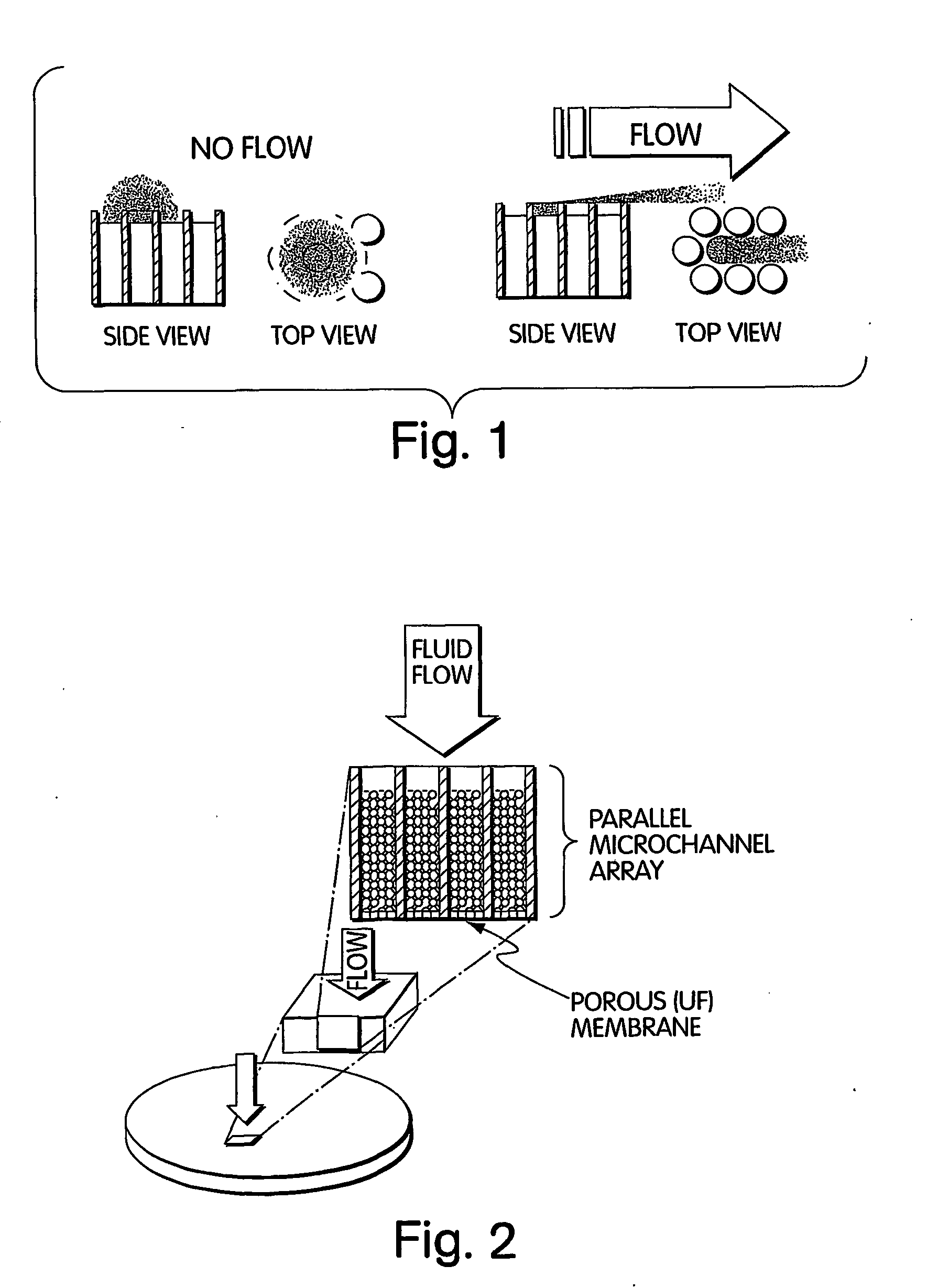
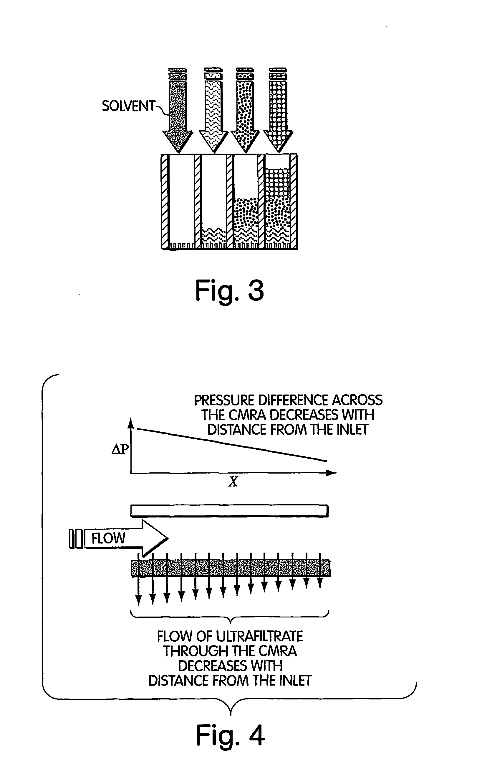
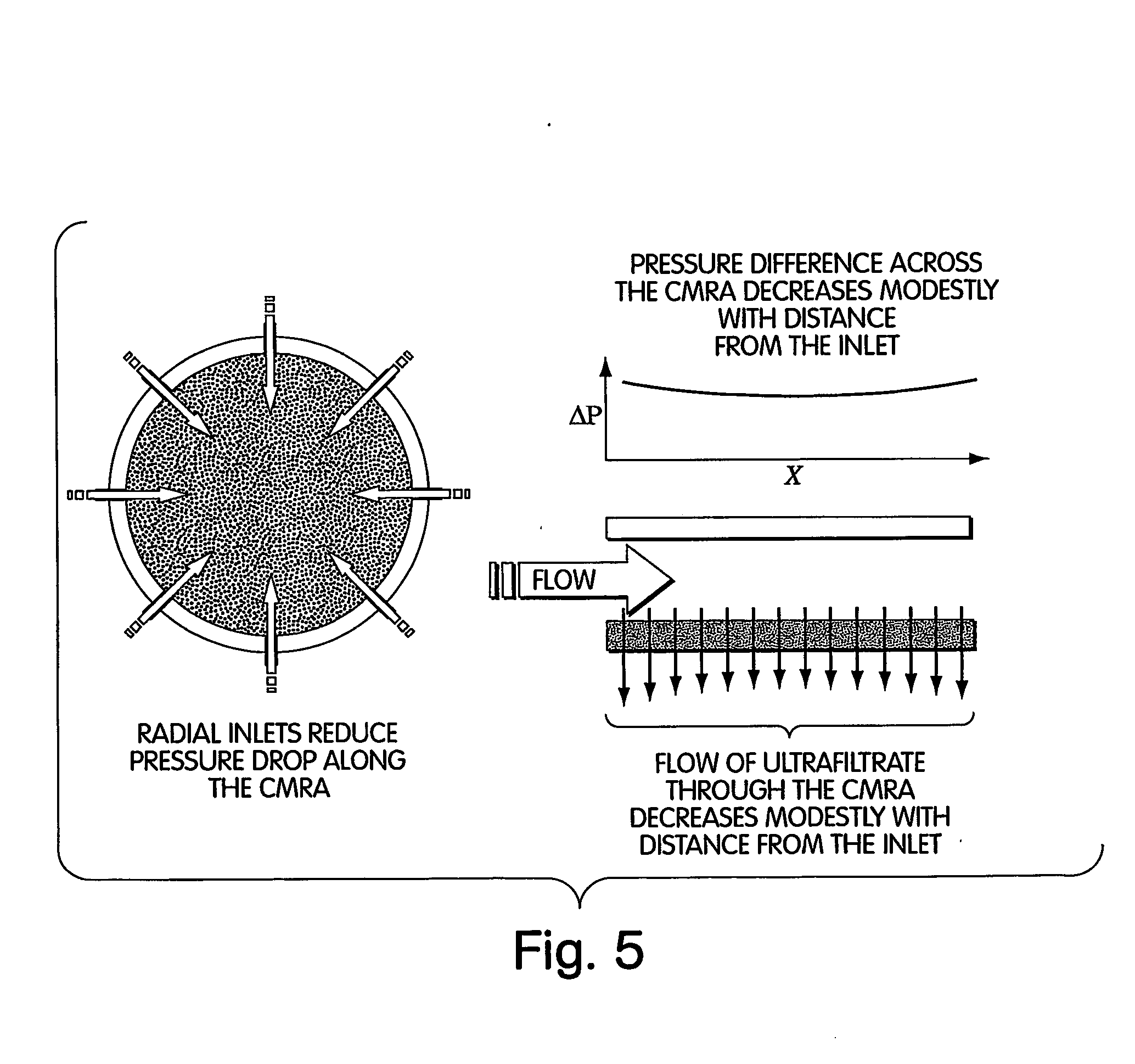
An ultrafiltration membrane is used to create a dense 2-D array of chemical reactions (“unconfined membrane reactor array” or UMRA) in which reactions are seeded by filtering a catalyst or reactant or enzyme onto the filter surface and whereby convective flow washes away laterally diffusing molecules before they contaminate adjacent reactions. Concentration polarization is necessary to create the packed columns of molecules for the UMRA followed by the sequential packing of molecules via concentration polarization to create stacked columns. Reagents are then flowed through a packed column of the UMRA for sequential processing of chemicals. The ultrafiltration membrane may then be bonded to a second, more porous membrane to provide mechanical support to the molecules concentrated by concentration polarization. The membrane is a Molecular / Por membrane (Spectrum Labs) or Anopore™ and Anodisc™ families of ultrafiltration membranes sold, for example, by Whatman PLC...


PUM

PropertyMeasurementUnit
pore sizeaaaaaaaaaa
pore sizeaaaaaaaaaa
molecular weightaaaaaaaaaa

Abstract

The present invention relates to the field of fluid dynamics. More specifically, this invention relates to methods and apparatus for conducting densely packed, independent chemical reactions in parallel in a substantially two-dimensional array. Accordingly, this invention also focuses on the use of this array for applications such as DNA sequencing, most preferably pyrosequencing, and DNA amplification.

Description

FIELD OF THE INVENTION The invention describes method and apparatus for conducting densely packed, independent chemical reactions in parallel in a substantially two-dimensional array comprising a porous filter. BACKGROUND OF THE INVENTION High throughput chemical synthesis and analysis are rapidly growing segments of technology for many areas of human endeavor, especially in the fields of material science, combinatorial chemistry, pharmaceuticals (drug synthesis and testing), and biotechnology (DNA sequencing, genotyping). Increasing throughput in any such process requires either that individual steps of the process be performed more quickly, with emphasis placed on accelerating rate-limiting steps, or that larger numbers of independent steps be performed in parallel. Examples of approaches for conducting chemical reactions in a high-throughput manner include such techniques as: Performing a reaction or associated processing step more quickly: Adding a catalyst Performing the ...

Claims


Application Information

Patent Timeline
Patent Type & Authority Applications(United States)
IPC IPC(8): C12N15/09B01D61/14B01D71/56B01J19/00C12M1/34C12M1/40C12Q1/68C12Q1/6869C40B40/06C40B40/10C40B60/14
CPCB01J19/0046C40B60/14B01J2219/00286B01J2219/00313B01J2219/00355B01J2219/00414B01J2219/00418B01J2219/00423B01J2219/00466B01J2219/00497B01J2219/005B01J2219/00524B01J2219/00576B01J2219/00605B01J2219/0061B01J2219/00612B01J2219/00626B01J2219/00641B01J2219/00648B01J2219/00659B01J2219/00677B01J2219/00702B01J2219/00722B01J2219/00725C12Q1/6869C40B40/06C40B40/10B01J2219/00283
Inventor WEINER, MICHAEL P.ATTIYA, SAIDCRENSHAW, HUGH C.ROTHBERG, JONATHAN M.MATSON, STEPHEN L.
Owner WEINER MICHAEL P
Why Eureka
Try Eureka