Optometry apparatus capable of measuring para-central defocus

a technology of para-central defocus and optometry, which is applied in the field of optometry, can solve the problems of the diopter of the retina beside the macular area not being corrected

Active Publication Date: 2019-11-19
SUZHOU SIHAITONG INSTR
View PDF14 Cites 0 Cited by
  • Summary
  • Abstract
  • Description
  • Claims
  • Application Information

AI Technical Summary

Benefits of technology

[0016]The above mentioned technical scheme employed by the present disclosure has the following advantages over the prior art: changing the propagation path of the first light beam by rotating the first reflecting mirror and the second reflecting mirror, and then changing the position of the light spot formed by the first light beam on the retina, two-dimensionally scanning the retina to obtain images reflected by respective areas of the retina, and thus implementing diopter measurement of the macular area and the areas beside the macular area of the retina, and achieving the diopter measurement of the para-central defocus.

Problems solved by technology

If the curvature beside the macular area of the retina does not coincide with the focal cambered surface of the human eye optical system, employing the traditional refractor to configure glasses correct the diopter of the macular area, but the diopter of the retina beside the macular area has not been corrected yet.

Method used


Image

  • Optometry apparatus capable of measuring para-central defocus

Examples


Embodiment Construction

[0019]In the following, the preferable embodiments of the present disclosure are explained in detail combining with the accompanying drawings so that the advantages and features of the present disclosure can be easily understood by the skilled persons in the art.

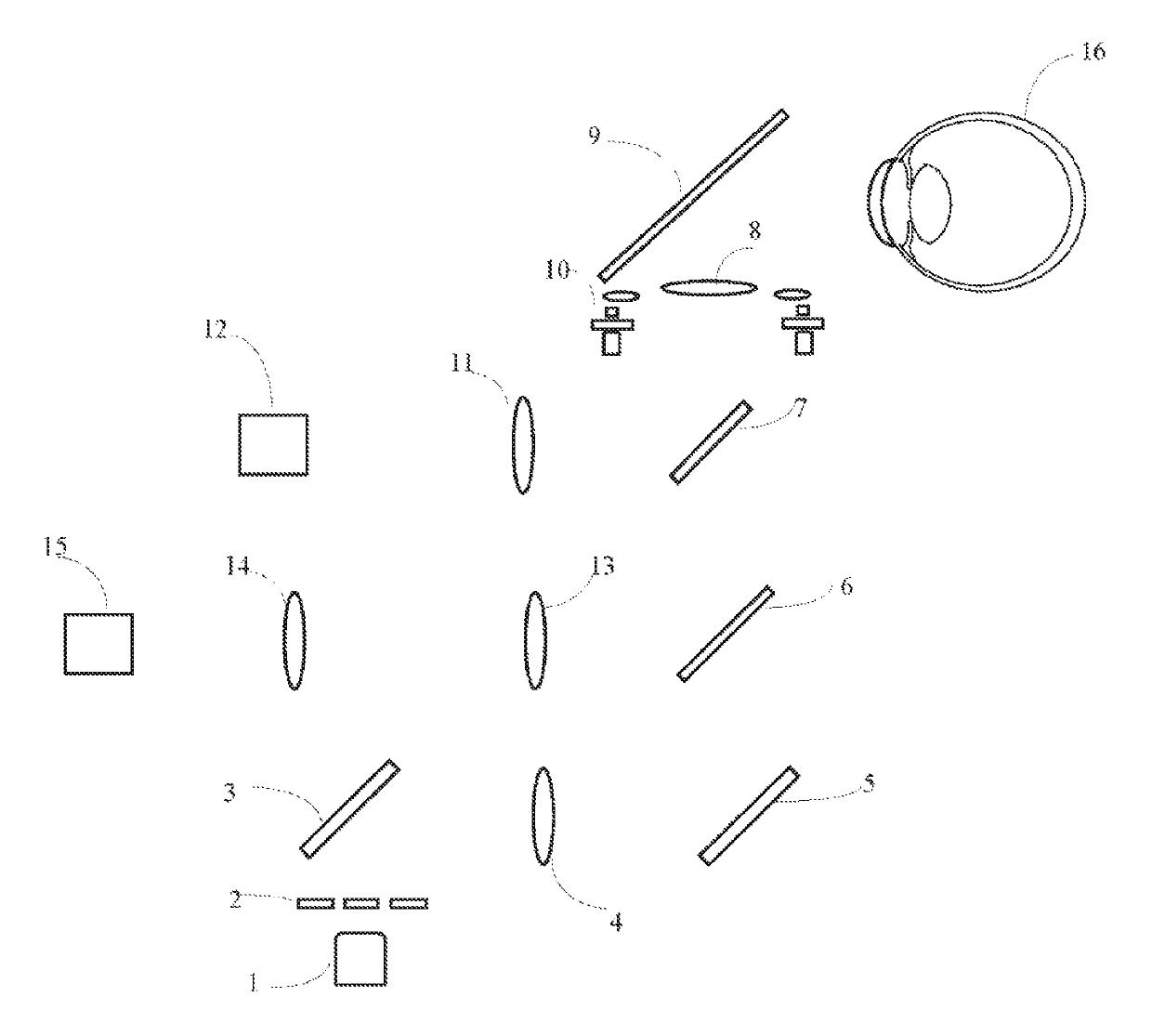
[0020]FIG. 1 shows an optometry apparatus capable of measuring para-central defocus of the present invention. Combining with FIG. 1, the optometry apparatus comprises a first light source 1, an annular diaphragm 2, a first reflecting mirror 3, a first lens group 4, a second reflecting mirror 5, a beam splitter 6, a first dichroic mirror 7, a second lens group 8, a second dichroic mirror 9, a second light source 10, a fifth lens group 11, a second photoelectric detector 12, a third lens group 13, a fourth lens group 14 and a first photoelectric detector 15.

[0021]In the FIG. 1 embodiment, the first light source 1, the annular diaphragm 2, the first lens group 4, the beam splitter 6, a first dichroic mirror 7, the third lens gr...


PUM


Abstract

Disclosed is an optometry apparatus capable of measuring para-central defocus, comprising a diopter measurement module. The diopter measurement module comprises a first light source (1) emitting a first light beam. The optometry apparatus also comprises a scanning module for adjusting the position of a light spot formed on the retina by the first light beam. The scanning module comprises a first reflecting mirror (3) and a second reflecting mirror (5) rotatably positioned in sequence in the emergent optical path of the first light source (1). The rotation axis of the first reflecting mirror (3) and the rotation axis of the second reflecting mirror (5) form therebetween an angle greater than 0 degree and less than 180 degrees.

Description

CROSS REFERENCE TO RELATED APPLICATIONS[0001]This application is a § 371 National Stage Application of PCT / CN2016 / 095559 filed Aug. 16, 2016, which claims priority to CN201510341685.0 filed Jun. 18, 2015, which are hereby incorporated by reference in their entirety.TECHNICAL FIELD OF THE INVENTION[0002]The present disclosure relates to the optometry field, in particular to an optometry apparatus capable of measuring para-central defocus.BACKGROUND OF THE INVENTION[0003]At present, when the optometry apparatus such as a traditional refractor proceeds optometry of a human eye, the light spot is projected on the macular area of the retina, the diopter measurement is only implemented on the macular area of the retina, and does not implemented on other area beside the macular area of the retina. The retina of a normal eye is spherical shaped, and when an object is imaged on the retina, the macular area of the retina and the macular periphery are just in the focal cambered surface of the ...

Claims


Application Information

Patent Timeline
Patent Type & Authority Patents(United States)
IPC IPC(8): A61B3/12A61B3/00
CPCA61B3/0008A61B3/12A61B3/103A61B3/107
Inventor XIE, PEICHU, RENYUANJIANG, BAICHUANZHOU, XINGTAOWANG, QINMEIZENG, JUNWENWEI, RUIHUAJIANG, QINZHONG, LISHEN, JI
Owner SUZHOU SIHAITONG INSTR
Why Eureka
Try Eureka