Joint structure of a bumper reinforcement and a side member

a technology of side members and bumper reinforcements, which is applied in the field of joint structure of bumper reinforcements and side members, can solve the problems of collision load not being absorbed as intended, collision load bending rigidity reduction of bumper reinforcements, and collision load not being sufficiently transmitted to the side members, etc., to achieve excellent advantageous effect, efficient transmission, and weight and cost reduction

Active Publication Date: 2019-11-19
TOYOTA JIDOSHA KK
View PDF22 Cites 1 Cited by
  • Summary
  • Abstract
  • Description
  • Claims
  • Application Information

AI Technical Summary

Benefits of technology

[0009]In consideration of the above circumstances, an object of the present disclosure is to obtain a joint structure of a bumper reinforcement and a side member that is capable of efficiently transmitting, to the side member, collision load inputted to the bumper reinforcement without hindering any compression deformation in the side member.

Problems solved by technology

Thus, when collision load is input to the bumper reinforcement, a pair of vehicle vertical direction walls of the bumper reinforcement deform so as to open in a direction to separate from each other, and it is possible that bending rigidity of the bumper reinforcement is reduced such that collision load cannot be sufficiently transmitted to the side member.
However, an increased number of fastening points hinders compression deformation of the front side member, and there is a possibility that collision load cannot be absorbed as intended.

Method used


Image

  • Joint structure of a bumper reinforcement and a side member
  • Joint structure of a bumper reinforcement and a side member
  • Joint structure of a bumper reinforcement and a side member

Examples


first exemplary embodiment

[0041

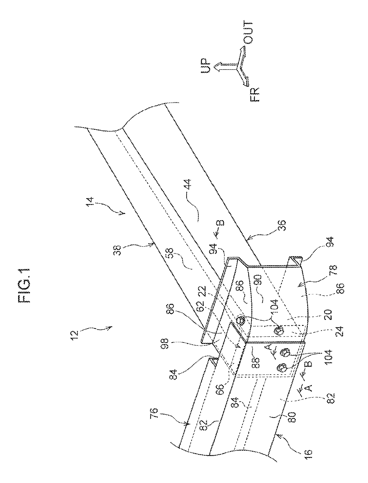
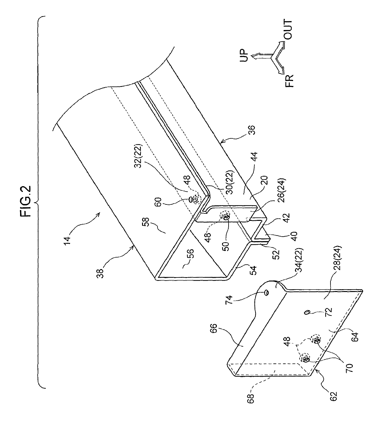
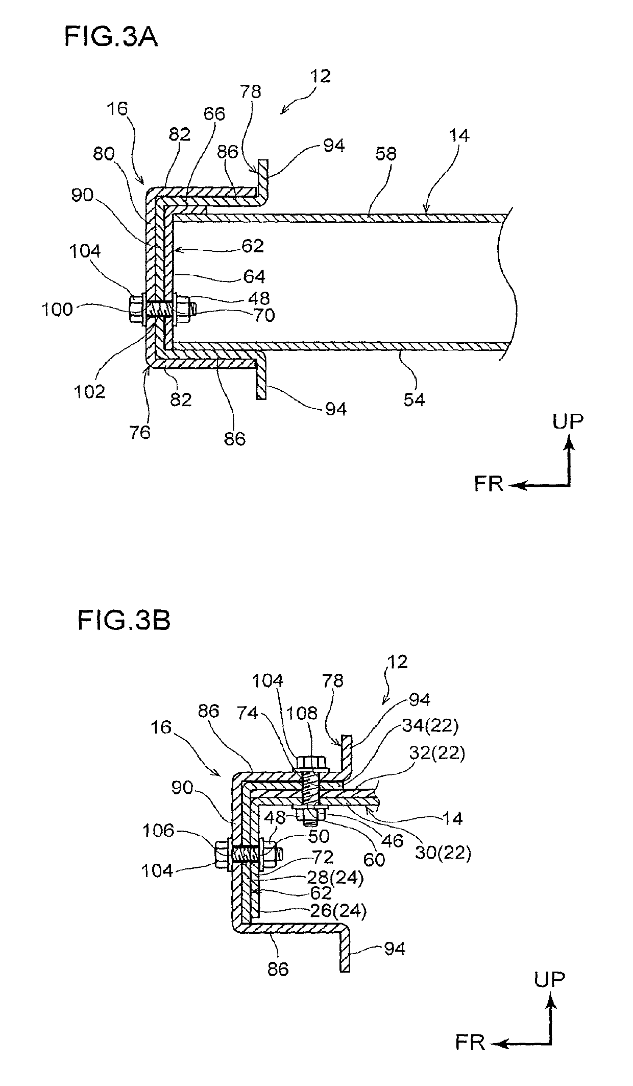
[0042]Explanation follows regarding a first exemplary embodiment of a joint structure of the bumper reinforcement and the side member according to the disclosure, with reference to FIG. 1 to FIG. 3. Note that in the drawings, the arrow FR indicates the vehicle front-rear direction front side, the arrow OUT indicates the vehicle width direction outer side, and the arrow UP indicates the vehicle vertical direction upper side.

[0043]As illustrated in FIG. 1, a joint structure of the bumper reinforcement and the side member joint structure 12 provided at a front section of a vehicle is configured including a vehicle width direction pair of front side members (referred to below as the side members) 14, and a bumper reinforcement 16 provided at the vehicle front side of the side members 14. Note that the joint structure of the bumper reinforcement and the side member 12 according to the present exemplary embodiment is configured with substantially left-right symmetry (left-right symme...

second exemplary embodiment

[0069

[0070]Next, explanation follows regarding a joint structure of the bumper reinforcement and the side member according to a second exemplary embodiment of the disclosure, with reference to FIG. 7 and FIG. 8. Note that configuration portions that are basically the same as those in the first exemplary embodiment are appended with the same reference numerals, and explanation thereof is omitted.

[0071]The joint structure of the bumper reinforcement and the side member 120 according to the second exemplary embodiment has the same basic configuration as that of the first exemplary embodiment except in that a bumper reinforcement 122 is configured by a single member.

[0072]Namely, as illustrated in FIG. 7, the bumper reinforcement 122 is, for example, manufactured from sheet steel, extends in the vehicle width direction, and is formed with a substantially hat-shaped open cross-section profile configured by a vertical wall 124 along the vehicle vertical direction, a pair of horizontal wal...

third exemplary embodiment

[0079

[0080]Explanation follows regarding a joint structure of the bumper reinforcement and the side member according to a third exemplary embodiment of the disclosure, with reference to FIG. 9. Note that configuration portions that are basically the same as those in the first exemplary embodiment described above are appended with the same reference numerals, and explanation thereof is omitted.

[0081]A joint structure of the bumper reinforcement and the side member 134 according to the third exemplary embodiment has the same basic configuration as that of the first exemplary embodiment, except in that a bracket 138 is provided to a side member 136.

[0082]Namely, as illustrated in FIG. 9, the side member 136 is configured including a side member inner panel 140 disposed at the vehicle width direction inner side, and a side member outer panel 142 disposed at the vehicle width direction outer side of the side member inner panel 140. The side member inner panel 140 extends along the vehicl...


PUM


Abstract

A joint structure of a bumper reinforcement and a side member, the joint structure comprising: a bumper reinforcement that is provided at a vehicle front-rear direction end portion of a vehicle so as to extend in a vehicle width direction, and that includes: a vertical wall and a pair of horizontal walls; a left and right pair of side members that are respectively provided at the vehicle inner side of the bumper reinforcement so as to extend in the vehicle front-rear direction with leading ends of the side members fastened to the vertical wall of the bumper reinforcement; and fastening extensions that are provided at the respective leading ends of the side members, that project out toward a vehicle width direction outer side with respect to a respective side member, and that are fastened to at least one of the horizontal walls of the bumper reinforcement.

Description

CROSS-REFERENCE TO RELATED APPLICATION[0001]This application is based on and claims priority under 35 USC 119 from Japanese Patent Application No. 2016-202930 filed on Oct. 14, 2016, the disclosure of which is incorporated by reference herein.BACKGROUND[0002]Technical Field[0003]The present disclosure is related to a joint structure of a bumper reinforcement and a side member.[0004]Related Art[0005]Japanese Patent Application Laid-Open (JP-A) No. 2012-236547 describes a vehicle body structure. This vehicle body structure is provided with bumper reinforcement extending along a vehicle width direction, a front side member extending along a vehicle front-rear direction, and a bumper stay provided at a lead end of the front side member.[0006]A front wall of the bumper stay is fastened to a front wall of the bumper reinforcement. Collision load inputted to the bumper reinforcement is accordingly transmitted to the front side member.[0007]However, in the configuration described in JP-A No...

Claims


Application Information

Patent Timeline
Patent Type & Authority Patents(United States)
IPC IPC(8): B60R19/00B60R19/02B60R19/24B60R19/18
CPCB60R19/023B60R19/18B60R19/24B62D21/02
Inventor IIZUKA, HIROHARU
Owner TOYOTA JIDOSHA KK
Why Eureka
Try Eureka