
Device for adjusting the capacity of a beverage cup

a technology for beverage cups and devices, applied in drinking vessels, internal fittings, instruments, etc., can solve problems such as social pressure, health problems, and drinking too much, and achieve the effect of avoiding alienation from others and being convenient to us

Active Publication Date: 2019-11-19
MYOFFICE LLC
View PDF8 Cites 6 Cited by
  • Summary
  • Abstract
  • Description
  • Claims
  • Application Information

AI Technical Summary

Benefits of technology

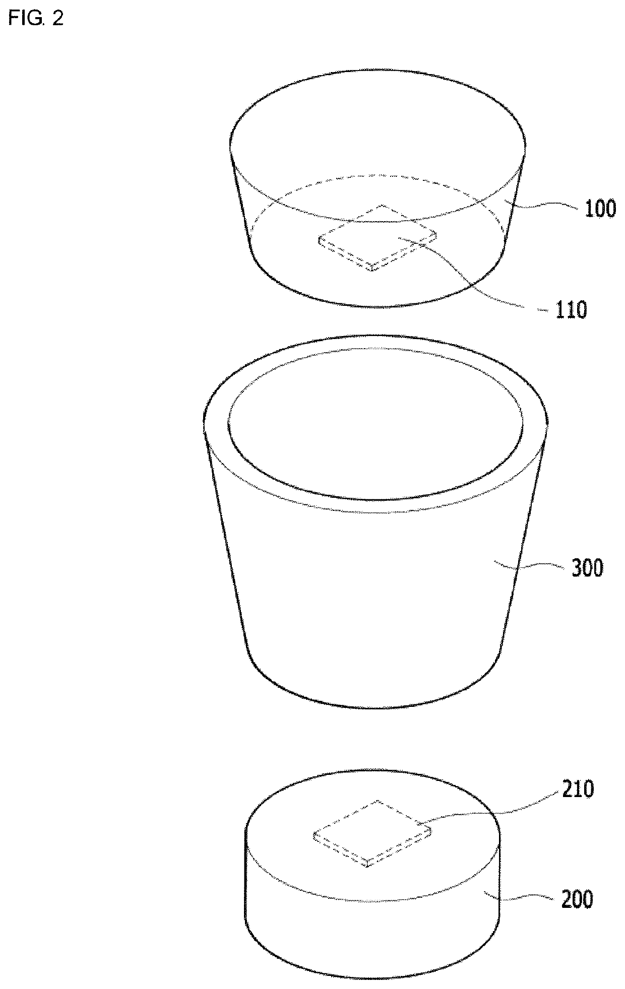
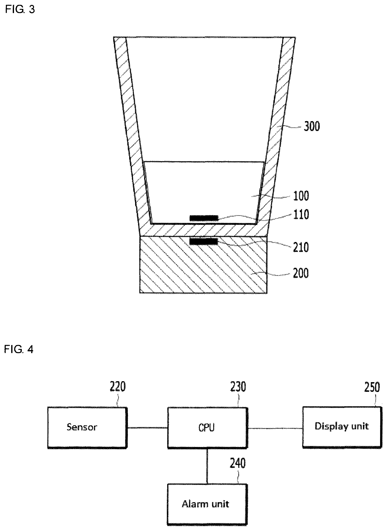
[0018]According to aspects of the present disclosure, the insertion unit and the outer fixed unit can be attached and detached by the magnets, the insertion unit allowing the user to adjust the volume of an alcoholic or nonalcoholic beverage being consumed from a cup provided at an existing restaurant and allowing one to drink at a similar pace with others while considering relative drinking capacity that reflects one's own personal drinking capacity.
[0019]In addition, it is possible to avoid the sense of alienation from others caused by differences in drinking capacity. Further, the structure is very simple, easy to use, and hygienic because the insertion unit is secured in the cup and independent from the outer fixed unit.

Problems solved by technology

This can put a great deal of social pressure on those with a relatively low drinking capacity, and women in particular, and can even cause health problems.
Therefore, although it would be preferable for everyone to drink according to their own drinking capacity, in order to form a social life or personal relations, many people often drink together using cups, i.e., in units of full cups, and end up drinking too much.
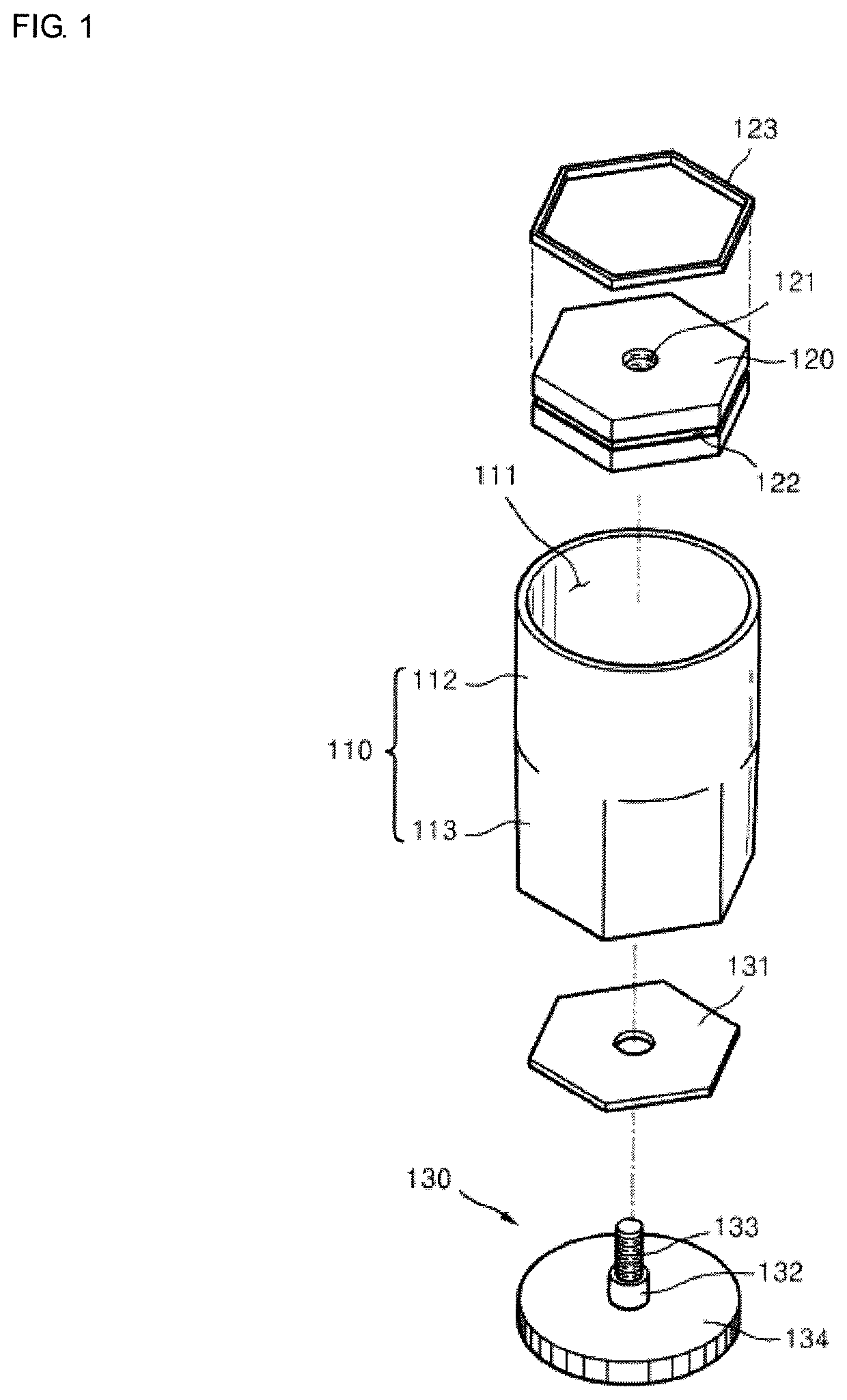
However, in order to use such a conventional cup when drinking an alcoholic beverage, a user needs to bring the main body 110 of the cup with the lift member 120 and the driving unit 130 mounted thereon, and this may cause alienation from others who are drinking with the user using another type of cup.
Therefore, the structure is complicated, and foreign substances easily adhere to the lift member 120 and the driving unit 130, which can be unsanitary and be very disadvantageous in hygiene management.

Method used


Image

  • Device for adjusting the capacity of a beverage cup
  • Device for adjusting the capacity of a beverage cup
  • Device for adjusting the capacity of a beverage cup

Examples


Embodiment Construction

[0024]Embodiments according to aspects of the present disclosure will be described in detail with reference to the accompanying drawings.

[0025]While the present disclosure is described herein by way of example using embodiments and illustrative drawings, those skilled in the art will recognize that the disclosure is not limited to the embodiments of drawing or drawings described, and are not intended to represent the scale of the various components. Further, some components that may form a part of the disclosure may not be illustrated in certain figures, for ease of illustration, and such omissions do not limit the embodiments outlined in any way. It should be understood that the drawings and detailed description thereto are not intended to limit the disclosure to the particular form disclosed, but on the contrary, the disclosure is to cover all modifications, equivalents, and alternatives falling within the scope of the present disclosure as defined by the appended claim. As used t...


PUM


Abstract

A device for adjusting the capacity of a beverage cup is provided. The device includes an insertion unit having at least a volume smaller than an interior volume of a cup and a shape in which a lower end portion of the insertion unit comes in contact with a bottom portion of the cup when inserted into the cup. The insertion unit includes a first magnet sealed in a bottom portion of the insertion unit. The device also includes an outer fixed unit to be placed under the cup. The outer fixed unit includes a second magnet sealed in the upper portion of the outer fixed unit for interacting with the first magnet of the insertion unit and securing the insertion unit to the cup by a magnetic force between the magnets.

Description

CROSS-REFERENCE TO RELATED APPLICATION[0001]This Application is a continuation of International Application No. PCT / KR2016 / 014930 filed on Dec. 20, 2016, which claims priority to Korean Application No. KR20150183168A filed in Dec. 21, 2015. The disclosures of these applications including the specifications, the drawings and the claims are hereby incorporated by reference in their entirety.FIELD OF THE INVENTION[0002]The embodiments discussed herein are related to a device for adjusting the capacity of a beverage cup, and more particularly, to a device which is installed in a cup when a user drinks an alcoholic or nonalcoholic beverage to adjust the capacity of the cup to fit the user's personal drinking capacity.BACKGROUND[0003]In the following description of the present disclosure, the case of a cup (glass) for drinking an alcoholic beverage will be described as an example.[0004]In Korean culture, there is a custom in which everyone who attends an event at which an alcoholic bevera...

Claims


Application Information

Patent Timeline
Patent Type & Authority Patents(United States)
IPC IPC(8): B65D21/08G01F23/20G01G19/52A47G19/22G01G19/414G01G23/36
CPCG01G19/4146B65D21/08G01G19/52A47G19/22A47G2200/22G01G23/36G01F23/20G01G17/04A47G19/2205A47G2200/106B65D25/02
Inventor LEE, JAE-SU
Owner MYOFFICE LLC
Learn More