Dual pathway riser and its use for production of petroleum products in multi-phase fluid pipelines

a technology of multi-phase fluid pipeline and riser, which is applied in the direction of branching pipes, sealing/packing, and well accessories, etc., can solve the problem of reducing the potential for any single large liquid slug to arrive at the surface facilities, and achieves the effect of improving the flow characteristics, reducing the cross-sectional area, and managing/improving the fluid flow characteristics

Active Publication Date: 2013-10-15
TECH COMMLIZATION
View PDF21 Cites 11 Cited by
  • Summary
  • Abstract
  • Description
  • Claims
  • Application Information

AI Technical Summary

Benefits of technology

[0011]Accordingly, it is an object of the present invention to overcome these and other drawbacks of the prior art by providing novel methods and devices for managing / improving the fluid flow characteristics in wells, risers and hilly terrain pipelines of oil, gas or condensate (cumulatively referred to here as petroleum) well systems by provision of an alternate tubular pathway for producing reservoir fluids that is internally reconfigured to affect the gas-liquid flow dynamics through the conduit / pipeline / riser / well, whereby the carrier phase (gas) more efficiently transports the carried phase (liquids or solids). To maintain and repair wells, risers and pipelines throughout subsea and land-based well production tubing systems, it is important to have access from the surface for pigging, fishing or coiled tubing operations and for land-based pipelines to have access end-to-end for pigging operations. The requirement of maintaining a sufficiently large pipeline / riser / well tubing diameter for such access precludes alteration in the design of the pipe itself as anticipated by the invention, thereby making it necessary to provide an alternate pathway.
[0012]Further, it is an object of the present invention to improve the flow characteristics in such alternate production wells, risers or hilly terrain pipelines of oil, gas or condensate wells by subdividing the flow into a plurality of individual fluid flows through substitution of an open pipe / conduit with one having a plurality of smaller parallel channels such as pipes placed inside, each such parallel pipe having a smaller cross-sectional area than the single open pipe, and preferably round inside. By virtue of reducing the diameter of the flow channel, the gas phase is less likely to slip past the liquid phase, thereby forcing an increase in the transfer of energy from the gas (carrier phase) to the liquid (carried phase), resulting in a lower producing gas-liquid ratio (GLR) downstream.
[0013]Further, it is an object of the present invention to improve the flow characteristics in wells, risers or hilly terrain pipelines of petroleum wells by virtually eliminating liquid slugging by way of dividing the flow into a plurality of smaller cross-section flows. Liquid slug length is highly correlated with the diameter of the flow pipeline, with smaller diameter pipes producing shorter liquid slugs, and so the invention will result in a smaller average length / mass for each slug. Second, such smaller liquid slugs from such plurality of parallel small riser columns arriving at the subsurface / surface facilities will each arrive independently. Greater number of independent pipes / tubes / flows causes a greater tendency to statistical averaging of the flow volume / mass exiting the riser at any given moment. This in turn reduces the potential for any single large liquid slug to arrive at the surface facilities. Third, a preferred design uses relatively small diameter (6 to 25 mm) internal pipes as compared to the 4-to 6-inch diameter pipes commonly used in practice. The flow through these small pipes will have the annular flow regime toward the top of the column and in a significant proportion down its length, given the effect of containment by virtue of the small diameter pipes. As the proportion of gas in the flow increases when more gas comes out of solution with increased elevation / distance (lower pressure) and as the gas phase expands with declining pressure (eventually resulting in annular flow), the recombined flow at the surface has a steady-state nature and therefore will not damage the surface facilities (separators, slug catcher, pipes, etc.).
[0014]Further, it is an object of the present invention to provide the capability to adjust the volumetric characteristics of the subsea production system over the life of the well to accommodate the reduced flow conditions experienced as reservoir depletion ensues. Early in the life of a gas-driven oil well for example, a large diameter pipe is beneficial to maximize production (high pressure and flux). But in lower flow rate conditions, as the gas phase void fraction increases throughout the system (and increasingly so downstream), decreasing the diameter of the production pipe increases the liquid proportion of the produced fluid (e.g. conversion to a smaller-diameter “velocity string” or “macaroni tubing” later in the life of an oil well to increase liquid production). The riser of the present invention, having a plurality of parallel small diameter pipes, is designed to be capable of being changed / replaced over the life of the well, substituting the one with a smaller diameter pipes (to increase transporting efficiency of free gas phase) or fewer pipes (adjust for less gas-liquid flux) over time to better optimize liquid production while minimizing gas production. In this vein, a subsea manifold connecting multiple wells to the entrance of multiple parallel high-efficiency risers of the invention, each such riser having a plurality of parallel small cross-section tubes / conduits inside, and the number of risers permitted to flow at any given time can be varied using valve control means based on the volume of the combined production of the wells, which is expected to vary over time. In this case, such dual pathway riser of the invention consists of more than one parallel valve-controlled riser / conduit having multiple parallel smaller-diameter internal passageways (in effect, a “multiple-pathway riser”). As such, the volumetric characteristics of the parallel riser system can be optimized over the life of the well(s) to maximize liquid production and to minimize the volume of gas or pressure differential needed to produce it, maximizing reservoir depletion.

Problems solved by technology

Second, such smaller liquid slugs from such plurality of parallel small riser columns arriving at the subsurface / surface facilities will each arrive independently.
This in turn reduces the potential for any single large liquid slug to arrive at the surface facilities.

Method used


Image

  • Dual pathway riser and its use for production of petroleum products in multi-phase fluid pipelines
  • Dual pathway riser and its use for production of petroleum products in multi-phase fluid pipelines
  • Dual pathway riser and its use for production of petroleum products in multi-phase fluid pipelines

Examples


first embodiment

[0056]Construction of a parallel MCS SCR riser can utilize any of the extrusion length / tubing configurations described in the Preferably, the lengths of each tube or extrusion with internal passageways should be as long as practicable to improve the efficiency of the two-phase flow effects conferred by the MCS riser. As a result, working with industry practice of pre-assembling 4-joint lengths of the riser, 4 bottom halves (half-shells) are first bolted together, then a pre-assembled bundle of MCS tubes / extrusions 4 joints long is placed into such 4 bolted bottom halves, then 4 half-shells tops are bolted to the bottom half-shells and to each other, and then all seams are welded together. If foam insulation is used, foam injection lines are integrated into the MCS extrusion / tubing bundle, such that after welding the shells together they can be withdrawn at a steady rate while injecting foam, thereby effectively providing foam access to the vacant spaces between the tubes or extrusi...

third embodiment

[0058]As per FIG. 12, this Third Embodiment of the invention consists of providing a dual flexible jumper line, providing fluid communication between the submerged platform (53) and the surface platform (55). One jumper line (51) is the original open-pipe type with the same termination fittings. The other jumper line (52) is an MCS pipeline (including a plurality of individual pipes, preferably round), such MCS small-diameter tubes preferably only integrated inside the rising / inclining part of the jumper pipeline, together with a pre-mixing device to more-evenly distribute the fluid phases prior to entering the plurality of individual tubes.

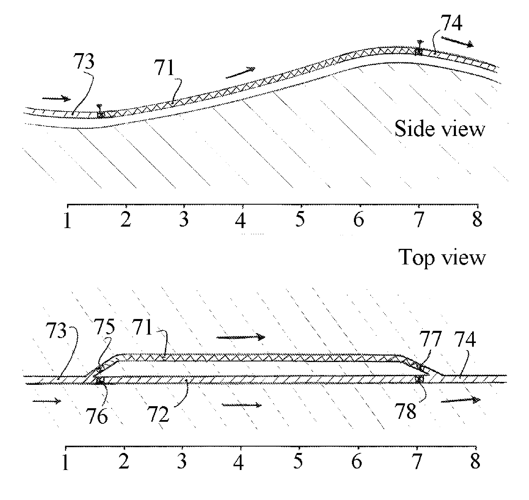
[0059]As is practice, the main riser terminates at a submerged platform with an output gooseneck-shaped termination fitting, where the attached flexible jumper line hangs from, such that the angle of its downward incline is similar to the gooseneck's incline, limiting strain. As per the invention, one design configuration is as shown in side and ...


PUM


Abstract

Disclosed is a tubing system for transporting a gas-liquid flow from a well to a production platform or processing facility. It includes a dual pathway section between the well and the production point having a first tubing portion and a second tubing portion. The second tubing portion includes a plurality of parallel channels so as to divide the multi-phase flow into a plurality of flows through individual channels. This is done to reduce flow slippage of the lower viscosity portion of the flow, which may lead to inefficiencies in flow characteristics, and often, undesirable cyclical variations in pressure and fluid volume. This is especially useful in inclined portions of the petroleum flow pipe system and along hilly terrain. The first round tubing portion is used for transporting the gas-liquid flow as well as for maintenance purposes, such as for pigging, fishing or coiled tubing operations.

Description

BACKGROUND[0001]To maintain and repair wells, risers and pipelines in land-based and subsea petroleum well production systems (tubing systems), it is important to have access from one end of the pipe / tube / riser / conduit / well / gathering line for pigging, fishing or coiled tubing operations. Unrefined petroleum products flowing inside metal pipes are known to build up deposits of scale, paraffin and asphaltine compounds on the walls of the pipes. Pigging operations to clean the pipes are performed as often as monthly and more, requiring production to be interrupted for about 2 days.[0002]Multi-phase fluid flowing through tubing systems is a common occurrence in petroleum production systems given that oil wells are usually co-produced with gas, and that gas wells are usually co-produced with water. Such multi-phase fluid from the well is transported through the tubing system to the production point, where the fluid is processed (separated into gas, oil and water). Such production point f...

Claims


Application Information

Patent Timeline
Patent Type & Authority Patents(United States)
IPC IPC(8): E21B7/12
CPCE21B17/01E21B17/203F16L11/133F16L11/22F16L41/03
Inventor GANELIN, BORISKENWORTHY, MICHAEL W.
Owner TECH COMMLIZATION
Why Eureka
Try Eureka