Rotating joint and painting machine

a technology of rotating joints and painting machines, which is applied in the direction of moving spraying equipment, spraying equipment, pipe elements, etc., can solve the problems of high cost of joint replacement and downtime, chemical corrosion, and impose downtime, so as to reduce the downtime and facilitate assembly, cleaning and maintenance of the joint components. , the effect of limiting downtim

Active Publication Date: 2019-11-26
CEFLA SOC COOP
View PDF9 Cites 0 Cited by
  • Summary
  • Abstract
  • Description
  • Claims
  • Application Information

AI Technical Summary

Benefits of technology

[0018]A first advantage of the present invention is that a painting process that is free from paint leakage is provided.
[0019]A second advantage is limiting downtime due to paint leakage.
[0020]A third advantage is the possibility of programming maintenance interventions, according to the evaluation of the degree of cloudiness of the liquid circulating in the low-pressure refrigerating circuit.
[0021]A fourth advantage is the fact that the shape of the joint assures an easy assembly of all its parts, and particularly of the seals of the high-pressure and low-pressure circuits. Moreover, cleaning and maintenance needed to refurbish the joint components is easier.
[0022]Further advantages and properties of the present invention are disclosed in the following description, in which exemplary embodiments of the present invention are explained in detail on the basis of the drawings:

Problems solved by technology

A typical drawback of such machines is that high pressure leads to paint leakage, which imposes downtime from damage of in-process articles and higher costs from the replacement of the joint and the downtime.
Moreover, they are often chemically corrosive, and sometimes are viscous.
During operation of the painting machine, friction is generated between the sealing elements and the contact surface of the shaft, which in turn generates high temperatures.
All together, these factors are strongly critical for the sealing of chambers, and lead to paint leakage over time which causes downtime for rotating joint maintenance.
The paint has to constantly move inside the pipes because some kinds of paint clog or create sediment if not moved.

Method used


Image

  • Rotating joint and painting machine
  • Rotating joint and painting machine
  • Rotating joint and painting machine

Examples


Embodiment Construction

[0034]In a first embodiment there are provided just one tank and one high-pressure circuit for one paint only.

[0035]In another embodiment, there are provided a plurality of distinct reservoirs for supplying paint, with a corresponding plurality of distinct high-pressure circuits, In the embodiment shown in the accompanying Figures, two distinct reservoirs and two distinct high-pressure circuits are provided, wherein two distinct paints can circulate. This embodiment allows the recirculation of the paints.

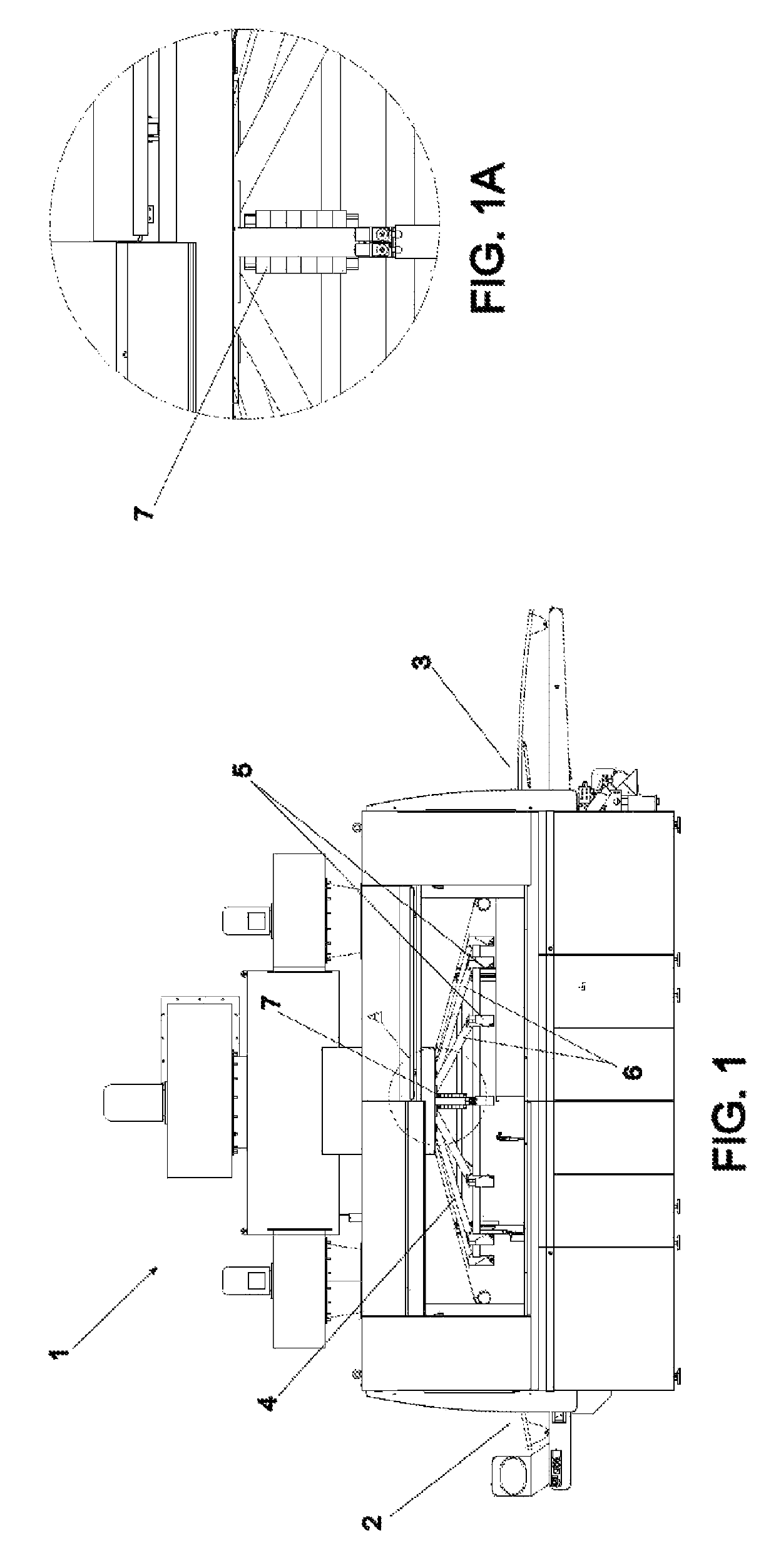
[0036]FIG. 1 shows a circular rotation spraying machine for the paint spraying of articles (not shown), including a painting rotary carrier 4. The articles to be painted enter through an entrance 2, are conveyed on a belt conveyor (not visible in the present Figure) under the painting rotary carrier 4, and leave painted through an exit 3,

[0037]The painting rotary carrier 4, fixed to a ceiling (not shown) of the machine 1, is provided with a plurality of spraying guns (not shown). Th...


PUM


Abstract

A paint spraying machine includes an apparatus for containing and removing the leakage of paint drops from a rotating joint, without the risk of damaging the article being sprayed, and thus without the need for downtime to replace sealing elements. The rotating joint includes a hollow shaft for distributing paint, a drum including a plurality of flanges that define separate chambers for different paints, a plurality of seals for separating the different paints in the different chambers which together form a high-pressure circuit, a low-pressure circuit to refrigerate the seals, improve their sealing and possibly intercept leaking paint, and a plurality of centering rings provide for correct assembly of the seals and the correct alignment of different flanges. The rings are hollow, and allow for the passage of the refrigerating / cleaning liquid under low pressure. A method for operating the machine includes containing and removing the leakage of paint drops from a rotating joint and distributing them back to the supplying tank of the refrigerating / cleaning liquid.

Description

[0001]The present invention relates to the technical field of machines for painting articles wherein spraying guns are fixed to a rotating carrier. In particular, it relates to a rotating joint for supplying paint to a spraying gun.Background of the Invention[0002]Machines for spraying paint are known in the art, which belong essentially to two types:[0003]oscillating spraying machines, wherein spraying guns are fixed on arms which oscillate with respect to the article to be painted; and[0004]circular rotation spraying machines, wherein spraying guns are fixed on a rotary carrier rotating above the article to be painted.[0005]Circular rotation spraying machines allow a simpler adjustment and a better paint transfer efficiency with respect to oscillating machines.[0006]Such machines are provided with a known rotating joint to supply paint to the machine spraying guns (typically from eight to twenty-four guns). Such a rotating joint supplies paint which often circulates inside a high-...

Claims


Application Information

Patent Timeline
Patent Type & Authority Patents(United States)
IPC IPC(8): B05B7/08F16L39/06B05B12/00B05B13/04B05B15/65
CPCB05B7/0846B05B13/0484F16L39/06B05B12/004B05B15/65B05B3/026B05B9/002B05B9/0413B05B12/00
Inventor PUNGETTI, CRISTIANCHIARINI, STEFANO
Owner CEFLA SOC COOP
Why Eureka
Try Eureka