
Machining devices

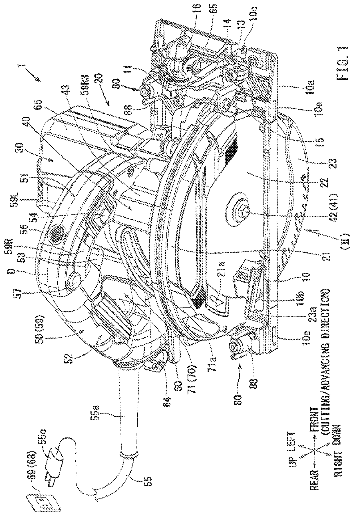
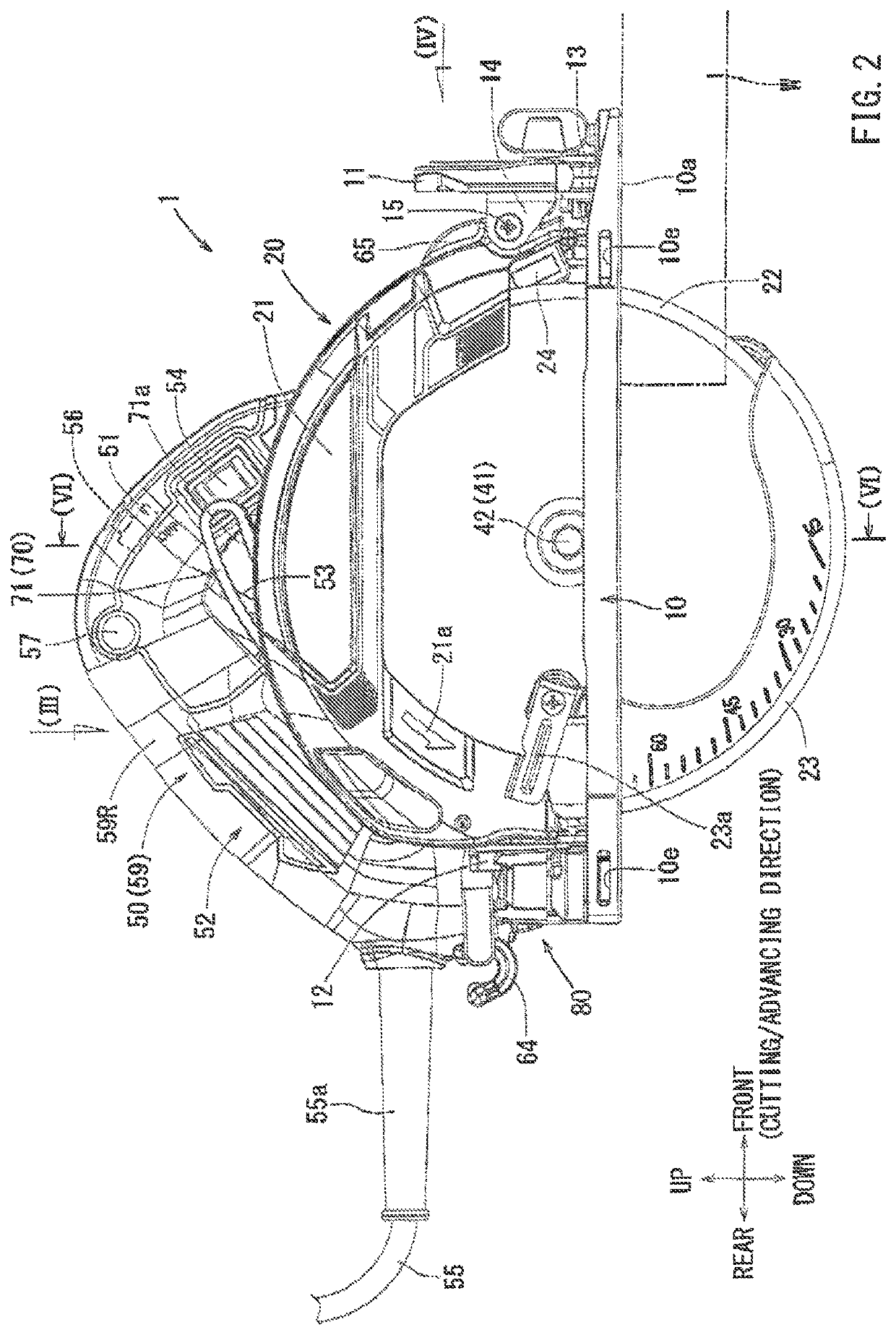
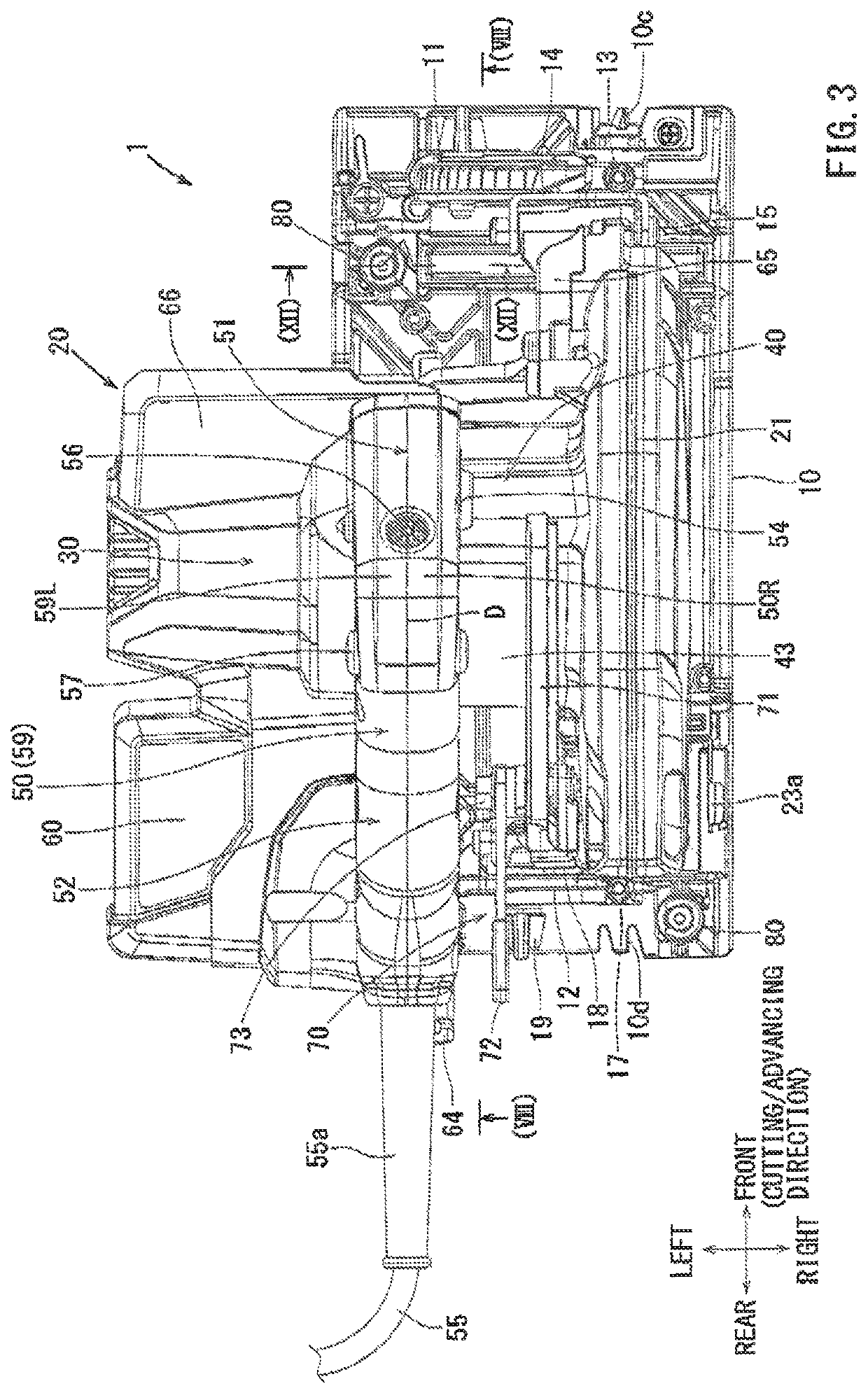
a technology of machining device and guide ruler, which is applied in the direction of metal sawing device, metal sawing accessories, manufacturing tools, etc., can solve the problems of difficulty in fine adjustment of the position of the guide ruler main body, possible offset of the connection bar, and restricted rotation of the pressing member

Active Publication Date: 2019-11-26
MAKITA CORP
View PDF36 Cites 0 Cited by
  • Summary
  • Abstract
  • Description
  • Claims
  • Application Information

AI Technical Summary

Benefits of technology

[0006]Thus, as a result of the mentioned deficiencies in the art, there is a need in the art to both prevent dent generation by the tip of the screw when screw-fastening the connection bar with the fixing screw, and also to prevent generation of an offset of the connection bar owing to the friction caused by the surface contact of the support member, thereby enabling true fine adjustment by the user of the position of the parallel guide ruler with respect to the base.
[0008]According to the embodiment, friction of the operation member with respect to the connection bar can be reduced by the friction reduction member. As a result, damage such as a dent (scar) etc. generation on the connection bar can be prevented. Furthermore, a positional offset of the connection bar can also be prevented, and the parallel guide ruler can be finely adjusted in a correct manner. A rolling ball bearing such as a ball bearing, as well as a bearing made of synthetic resin with a low friction coefficient or a bearing such as a bearing metal made of oil-impregnated metal can be used as the friction reduction member. Furthermore, lubricant oil such as grease can be applied to the tip end of the operation member (a pressing member with respect to the connection bar) in order to reduce friction.
[0010]According to such an embodiment, the pressing member that is rotated with respect to the operation member is brought into contact with the connection bar, and in this state of contact the connection bar is pressed by the motive force caused by rotation of the operation member. In the prior art, a tip end of the fixing screw directly presses the connection bar in order to fix the parallel guide ruler. In contrast, in the present embodiment, the connection bar can be fixed via the pressing member by indirectly applying the motive force caused by rotation of the operation member. As a result, unlike in the prior art, damage such as the dent (scar) generation may be prevented on the connection bar. Furthermore, since the pressing member as the friction reduction member is rotatably supported by the operation member, in a stage where the pressing member is pressed by the connection bar by rotation of the operation member, rotation of the pressing member is restricted. By virtue of the rotation of the pressing member being restricted, the positional offset of the connection bar is also restricted. As a result, the position of the parallel guide ruler can be finely adjusted in a correct manner.
[0016]According to such an embodiment, damage such as the dent (scar) generation with respect to the parallel guide ruler can be reliably prevented.
[0018]According to such an embodiment, friction of the operation member with respect to the connection bar is reduced by the friction reduction member. As a result, damage such as the dent (scar) generation is prevented on the connection bar. Furthermore, the positional offset of the connection bar is also prevented and thus the attaching position of the auxiliary tool with respect to the base can be finely adjusted in a correct manner. A rolling ball bearing such as a ball bearing, as well as a bearing made of synthetic resin with a low friction coefficient, or a bearing such as a bearing metal made of oil-impregnated metal, can be used as the friction reduction member. Furthermore, lubricant oil such as grease can be applied to the tip end of the operation member (a pressing member with respect to the connection bar) in order to reduce friction.
[0020]According to such an embodiment, the above-discussed effect can be obtained by the tool-fixing device for fixing the long guide ruler adaptor. The long guide ruler adaptor is the auxiliary tool that is used when the long guide ruler is attached to the portable machining device, and the portable machining device can be guided along the long guide ruler via the auxiliary tool.

Problems solved by technology

However, the guide ruler fixing method disclosed in Japanese Laid-Open Patent Publication No. 2006-159786 may cause the following failures owing to the structure where the tip of the fixing screw presses the connection bar directly.
Because of this configuration, it might be difficult to finely adjust the position of the guide ruler main body.
However, there still remains a possibility for an offset of the connection bar to occur owing to the friction caused by the surface contact of the support member.
Furthermore, since the pressing member as the friction reduction member is rotatably supported by the operation member, in a stage where the pressing member is pressed by the connection bar by rotation of the operation member, rotation of the pressing member is restricted.
As a result, the positional offset of the connection bar is restricted.

Method used


Image

  • Machining devices
  • Machining devices
  • Machining devices

Examples


Embodiment Construction

[0042]The detailed description set forth below, when considered with the appended drawings, is intended to be a description of exemplary embodiments of the present invention and is not intended to be restrictive and / or to represent the only embodiments in which the present invention can be practiced. The term “exemplary” used throughout this description means “serving as an example, instance, or illustration,” and should not necessarily be construed as preferred or advantageous over other exemplary embodiments. The detailed description includes specific details for the purpose of providing a thorough understanding of the exemplary embodiments of the invention. It will be apparent to those skilled in the art that the exemplary embodiments of the invention may be practiced without these specific details. In some instances, these specific details refer to well-known structures, components and / or devices that are shown in block diagram form in order to avoid obscuring more significant a...


PUM

PropertyMeasurementUnit
thicknessaaaaaaaaaa
motive forceaaaaaaaaaa
frictionaaaaaaaaaa

Abstract

A pressing member is rotatably supported by a fixing screw shaft via a ball bearing. The pressing member is made of synthetic resin and is larger in diameter compared to that of the fixing screw shaft. A connection bar is pressed by the pressing member by fastening the fixing screw shaft, and the position of the connection bar is thereby fixed. Because the pressing member has a large diameter, a dent is not generated on the connection bar. Furthermore, because the pressing member is not rotated in the fixed position, the position of the connection bar is not offset, enhancing the ability of fixing the connection bar with precise adjustment.

Description

CROSS-REFERENCE[0001]This application claims priority to Japanese patent application serial number 2016-097957, filed on May 16, 2016, and to Japanese patent application serial number 2017-048362, filed on Mar. 14, 2017, where the contents of both are incorporated herein by reference in their entirety.TECHNICAL FIELD[0002]The present invention generally relates to a machining device and / or a machining apparatus / tool such as, for example, a portable cutting device, used for cutting a material to be cut (work piece), such as a wooden material, etc.BACKGROUND ART[0003]In some of the portable cutting devices known in the art, a user performs a cutting work of a material to be cut (work piece) by moving the cutting device placed on the material to be cut (work piece). These types of cutting devices may include a base that is brought into contact with an upper surface of the material to be cut (workpiece) and a cutting device main body that is supported above an upper surface of the base....

Claims


Application Information

Patent Timeline
Patent Type & Authority Patents(United States)
IPC IPC(8): B23D59/00B23D45/16B27B9/04
CPCB23D45/16B27B9/04B23D59/002
Inventor NAKASHIMA, TATSUO
Owner MAKITA CORP
Learn More