Transcutaneous electrical nerve stimulator

a technology of electrical nerve stimulation and transcutaneous nerve, which is applied in the field of transcutaneous electrical nerve stimulation, can solve the problems of inflexibility of conventional electrode patches, identification of some problems or limitations, and limitations on comfort and connection

Active Publication Date: 2019-12-03
LEFKOVITZ JOSHUA A
View PDF4 Cites 1 Cited by
  • Summary
  • Abstract
  • Description
  • Claims
  • Application Information

AI Technical Summary

Problems solved by technology

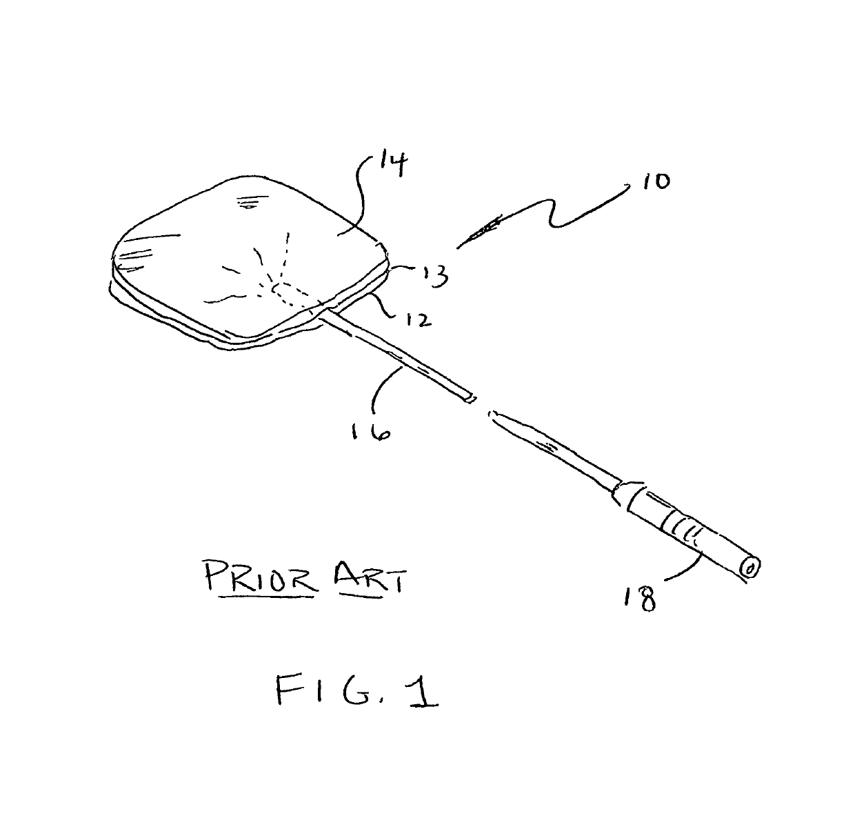
In the treatment of chronic pain, the identification of the pain causation, and the appropriate application of a therapeutic to cause a beneficial effect without adverse side effects has long been a troublesome area of medical practice.
This ability for a patient to be able to wear such a portable device on an ongoing basis results in the identification of some problems or limitations.
Attachment of electrodes to an anatomical surface over a long period of time creates limitations on both comfort and connection.
The lack of flexibility of conventional electrode patches provide resistance to movement that can increase irritation or decrease conductivity.
This can be especially at issue when used at high movement anatomical surfaces such as joints.
Where the anode and cathode are made using a silver substrate, an unbalanced electrical field can form with more charge accumulation near the anode than cathode (or vice versa).
Such chemical reactions create dirt and corrosion on the surface of the silver substrate which is both unsightly and can adversely affect impedence of the electrodes.

Method used


Image

  • Transcutaneous electrical nerve stimulator
  • Transcutaneous electrical nerve stimulator
  • Transcutaneous electrical nerve stimulator

Examples


Embodiment Construction

[0025]The best mode for carrying out the invention is presented in terms of its preferred embodiment, herein depicted within the Figures. It should be understood that the legal scope of the description is defined by the words of the claims set forth at the end of this patent and that the detailed description is to be construed as exemplary only and does not describe every possible embodiment since describing every possible embodiment would be impractical, if not impossible. Numerous alternative embodiments could be implemented, using either current technology or technology developed after the filing date of this patent, which would still fall within the scope of the claims.

[0026]It should also be understood that, unless a term is expressly defined in this patent there is no intent to limit the meaning of that term, either expressly or by implication, beyond its plain or ordinary meaning, and such term should not be interpreted to be limited in scope based on any statement made in an...


PUM


Abstract

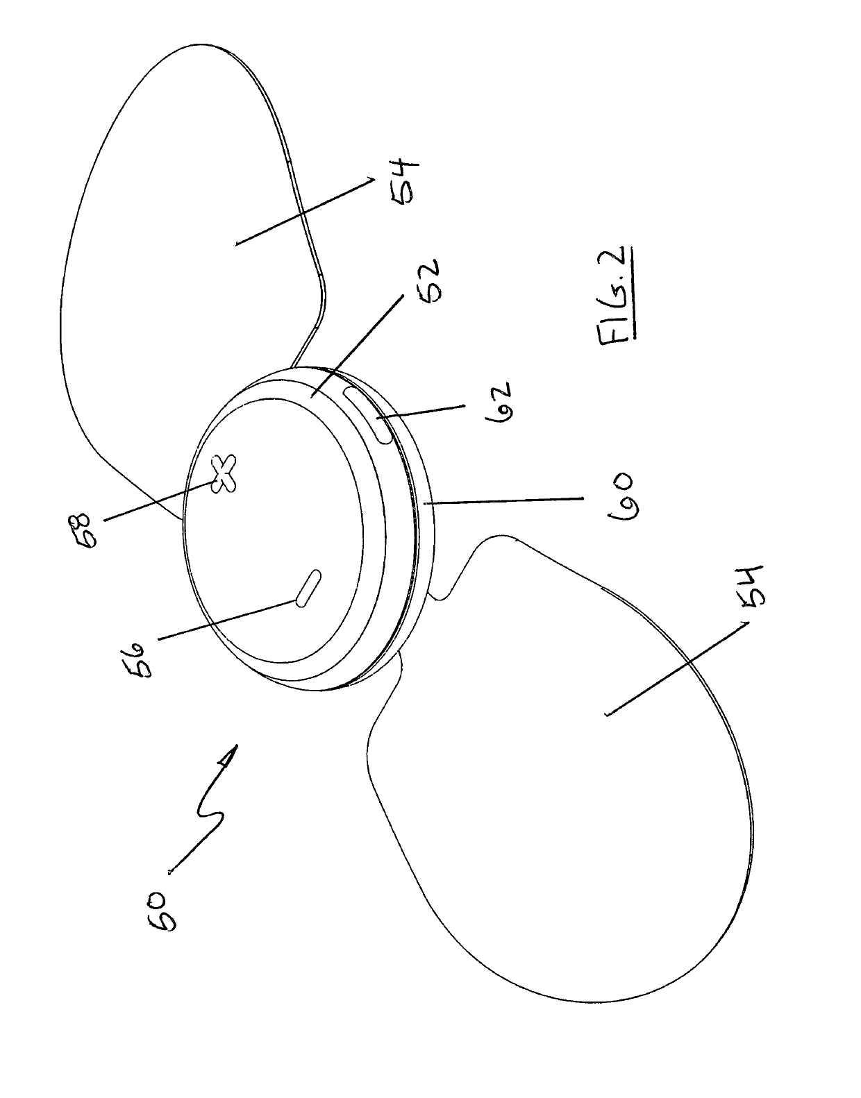
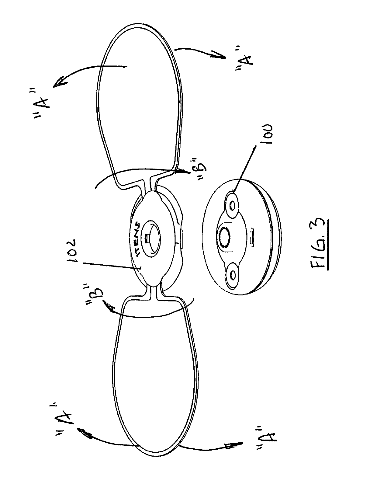
A TENS system is provided having an electrode element design accommodating improved motion mechanics and maneuverability while maintaining electrical contact. An electrode having a soft wing construction is provided such that a multi-planar flexibility is provided during operation. A range of motion hinge provides and positions at a central area of a winged configuration a housing such that both a rotational movement and an angular movement may occur while maintaining continuous, direct contact with the TENS electronics within the housing. A selected die-cut pattern of a number of designs may form a stepped-in wing configuration may further contribute to a lateral flexibility of the wings.

Description

RELATED APPLICATIONS[0001]The present invention claims the benefit of U.S. Provisional Application 62 / 290,989 filed on Feb. 4, 2016 and U.S. Provisional Application 62 / 426,244 filed on Nov. 24, 2016, both incorporated by reference as if fully rewritten herein.BACKGROUND OF THE INVENTION1. Field of the Invention[0002]The present invention relates to transcutaneous electrical nerve stimulation (“TENS”) systems and, more particularly, to an improved TENS system that incorporates functional anatomical shaped electrodes that enables bio-movement.2. Description of the Related Art[0003]In the treatment of chronic pain, the identification of the pain causation, and the appropriate application of a therapeutic to cause a beneficial effect without adverse side effects has long been a troublesome area of medical practice. “Chronic pain” is a diagnosis that is less a true diagnosis of the physiological condition than a symptomatic diagnosis describing a chronic condition.[0004]One treatment for...

Claims


Application Information

Patent Timeline
Patent Type & Authority Patents(United States)
IPC IPC(8): A61B5/00A61N1/04A61N1/36
CPCA61N1/36021A61B5/4824A61N1/0492A61N1/0456A61B5/1118
Inventor LEFKOVITZ, JOSHUA A.
Owner LEFKOVITZ JOSHUA A
Why Eureka
Try Eureka