Image forming apparatus, image forming method and non-transitory computer-readable recording medium encoded with image forming program

a technology of image forming and image forming, which is applied in the direction of electrographic process apparatus, corona discharge, instruments, etc., can solve the problems of long time required for image formation, wasteful consumption of toner, and inability to recover from the delay of a delayed sh

Active Publication Date: 2019-12-03
KONICA MINOLTA INC
View PDF10 Cites 0 Cited by
  • Summary
  • Abstract
  • Description
  • Claims
  • Application Information

AI Technical Summary

Benefits of technology

[0005]However, according to the image forming apparatus described in Japanese Patent Laid-Open No. 2003-167485, it is impossible to recover from the delay for a delayed sheet at a point of time when a delay behind the retransfer timing is detected. Therefore, it is necessary to newly form the same image after toner formed on the intermediate transfer body is discarded, and thus there is a problem that toner is wastefully consumed and long time is required for image formation.

Problems solved by technology

However, according to the image forming apparatus described in Japanese Patent Laid-Open No. 2003-167485, it is impossible to recover from the delay for a delayed sheet at a point of time when a delay behind the retransfer timing is detected.
Therefore, it is necessary to newly form the same image after toner formed on the intermediate transfer body is discarded, and thus there is a problem that toner is wastefully consumed and long time is required for image formation.

Method used


Image

  • Image forming apparatus, image forming method and non-transitory computer-readable recording medium encoded with image forming program
  • Image forming apparatus, image forming method and non-transitory computer-readable recording medium encoded with image forming program
  • Image forming apparatus, image forming method and non-transitory computer-readable recording medium encoded with image forming program

Examples


first embodiment

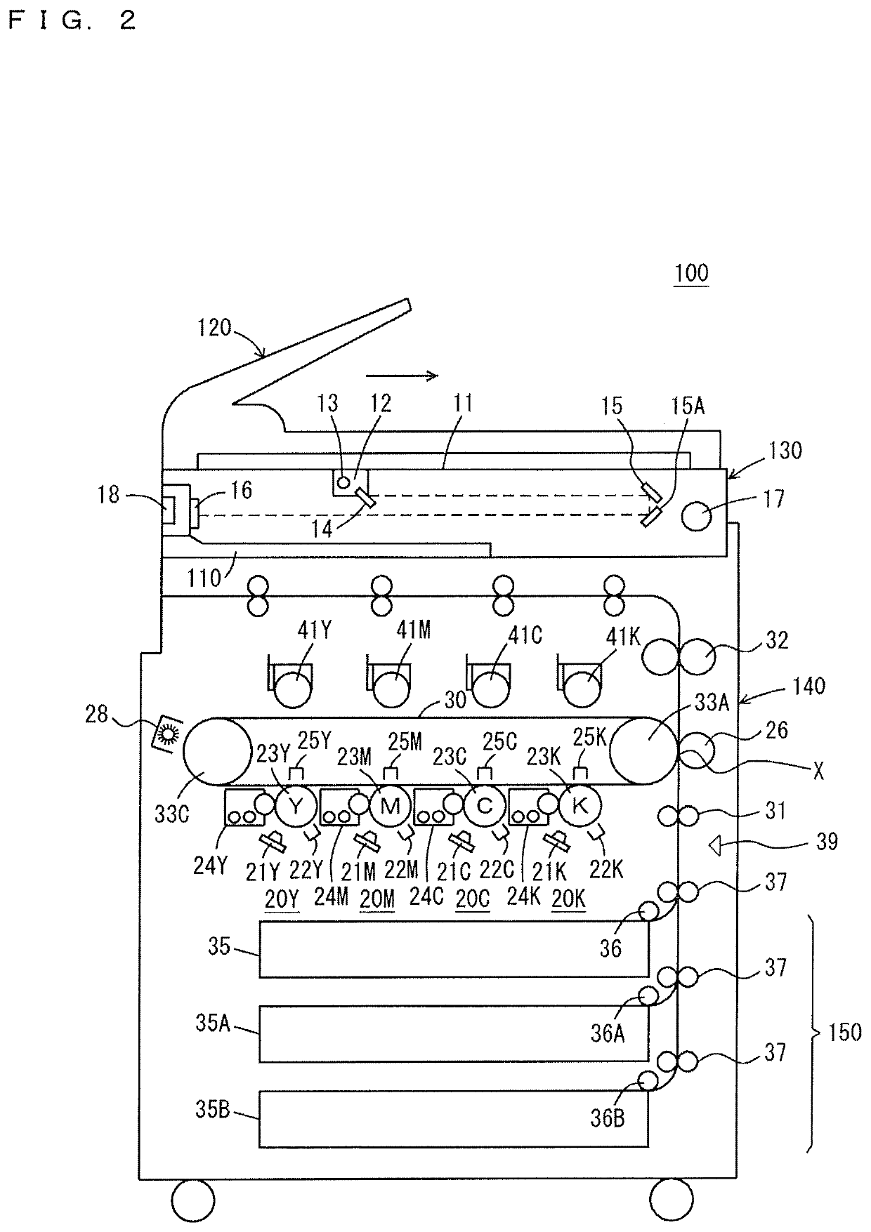
[0099]FIG. 9 is a diagram showing an example of a distance and a conveyance period for every path according to the embodiments. Referring to FIG. 9, a conveyance path of the toner image is a path where the toner image is conveyed (a toner conveyance distance L1), which is between a position where the photoreceptor drum 23Y is exposed and the transfer position X. The toner conveyance distance L1 is set to 300 mm, and the toner conveyance period T1 is set to 1000 ms. It is here assumed that the toner conveyance speed S is set to 300 mm / s. A paper path 1 is a path between the timing roller 31 and the transfer position X (a paper conveyance distance L2). The paper conveyance distance L2 is set to 100 mm, and the paper conveyance period T2 is set to 333 ms.

[0100]A paper path 2 is a path where the sheet is conveyed, which is between the timing sensor 39 and the timing roller 31. The paper path 2 is set to 50 mm in distance. A period when a tip of the sheet moves in the paper path 2 become...

first modified embodiment

[0119]The MFP 100 according to the first modified embodiment is configured to allow missing of an image.

[0120]FIG. 14 is a block diagram showing an example of functions of a CPU included in the MFP according to the first modified embodiment. Functions shown in FIG. 14 are different from functions shown in FIG. 4 in a point where a deleting disabled area determining portion 59 is added, and the image position determining portion 61 is changed to an image position determining portion 61A. Other functions are the same as shown in FIG. 4, and therefore, the description thereof will not repeated.

[0121]The deleting disabled area determining portion 59 determines a deleting disabled area in a sheet based on the print data input from the print data generating portion 51. The deleting disabled area is an area within the sheet on which a toner image is scheduled to be formed based on the print data, and is an area necessary to be included in the sheet for the toner image. The deleting disable...

second embodiment

[0126]FIG. 16 is a diagram schematically showing an example of the print data according to the first modified embodiment. FIG. 16 shows a state where the toner image is superimposed on a sheet. A lateral direction of the sheet is a sub scanning direction in which the sheet is conveyed. The left side of the sheet is a tip of the conveyance direction. An area of the toner image is shown by hatching. The sheet is divided in the sub scanning direction into eleven areas. Here, each of the eleven areas has 20 mm length in the sub scanning direction. The eleven areas are provided with area numbers starting from 1 to 11 in order from the left.

[0127]FIG. 17 is a diagram showing an example of toner distribution in a plurality of areas. Referring to FIG. 17, a toner occupancy ratio and a maximum value of toner density for each of yellow (Y), magenta (M), cyan (C) and black (K) are indicated for each of the eleven areas shown in FIG. 16. The toner occupancy ratio is a ratio occupied by a pixel ...


PUM


Abstract

An image forming apparatus includes an image forming controller forming a toner image on an image carrying member, and transferring at a transfer position the toner image formed on the image carrying member onto a sheet being conveyed on a conveyance path, and a hardware-processor. The hardware-processor determines an image position indicating a position for an image to be formed on the sheet, determines a grace period based on the image position, stops the sheet at a waiting position on an upstream side from the transfer position, restarts paper conveyance at a second point when a predetermined period elapses from a first point of starting formation of the toner image on the image carrying member, and conveys the sheet to the transfer position if paper conveyance can be restarted before the grace period elapses from the second point though paper conveyance cannot be restarted at the second point.

Description

[0001]Japanese Patent Application No. 2016-227044 filed on Nov. 22, 2016, including description, claims, drawings, and abstract, the entire disclosure is incorporated herein by reference in its entirety.BACKGROUNDTechnological Field[0002]The present invention relates to an image forming apparatus, an image forming method, and an image forming program. More specifically, the present invention relates to an image forming apparatus which forms an image on a sheet by using toner, an image forming method executed by the image forming apparatus, and a non-transitory computer-readable recording medium encoded with an image forming program which is executed by the image forming apparatus.Description of the Related Art[0003]In these years, an image forming apparatus represented by a multi-function peripheral (hereinafter, referred to as an “MFP”) includes a photoreceptor drum and a developing device which develops with toner an electrostatic latent image formed on the photoreceptor drum, and...

Claims


Application Information

Patent Timeline
Patent Type & Authority Patents(United States)
IPC IPC(8): G03G15/02G03G15/08G03G21/14
CPCG03G15/0887G03G21/14G03G15/02G03G15/0806G03G15/6558G03G15/6564
Inventor HITAKA, MASATOSHI
Owner KONICA MINOLTA INC
Why Eureka
Try Eureka