Power linear and switching regulators commonly controlled for plural loads

a technology of power linear and switching regulator, which is applied in the direction of electric variable regulation, process and machine control, instruments, etc., can solve the problems of significantly reducing efficiency when a load consumes, wasteful electric power consumption, and relatively high power consumption of the regulator, and achieves the effect of less power

Inactive Publication Date: 2007-10-30
RICOH ELECTRONIC DEVICES CO LTD
View PDF6 Cites 0 Cited by
  • Summary
  • Abstract
  • Description
  • Claims
  • Application Information

AI Technical Summary

Benefits of technology

[0004]One method for reducing power consumed by an apparatus includes dropping a voltage supplied to the apparatus. Recent apparatuses are tending to become multi-functional and various types of circuits are activated at various operation modes depending on the usage. In addition, another method includes dropping a voltage of the apparatus in response to various kinds of circuits. A power supply voltage meeting such performance requirements varies. Generally, to avoid a complicated power supply circuit, the power supply circuits are set for a circuit that requires the highest voltage. Such power supply circuits also need to supply the voltage to a circuit that satisfactorily performs even with a low voltage, resulting in the consumption of wasteful electric power.

Problems solved by technology

Such power supply circuits also need to supply the voltage to a circuit that satisfactorily performs even with a low voltage, resulting in the consumption of wasteful electric power.
The switching regulator provides a high efficiency in a rated load, high ripple of an output voltage and a high noise during operation, and relatively high power consumed by the regulator, thereby significantly reducing efficiency when a load consumes less power.
Further, the switching regulator has a slightly slow response time in response to a rise time, input voltage fluctuations, and load variations so that an output voltage stability is limited.
Meanwhile, with large load current, the series regulator provides a low efficiency due to a high power consumed by a control transistor, low ripple of an output voltage, and low noise during operation.
With a low output voltage, the series regulator 102 instead of the switching regulator 101 is not used and continues to activate the switching regulator 101 having significantly decreased efficiency, resulting in the consuming of wasteful electric power.
Moreover, under certain operating conditions in certain kinds of loads, a decrease in the output voltage can further decrease the electric power consumption.

Method used


Image

  • Power linear and switching regulators commonly controlled for plural loads
  • Power linear and switching regulators commonly controlled for plural loads
  • Power linear and switching regulators commonly controlled for plural loads

Examples


Embodiment Construction

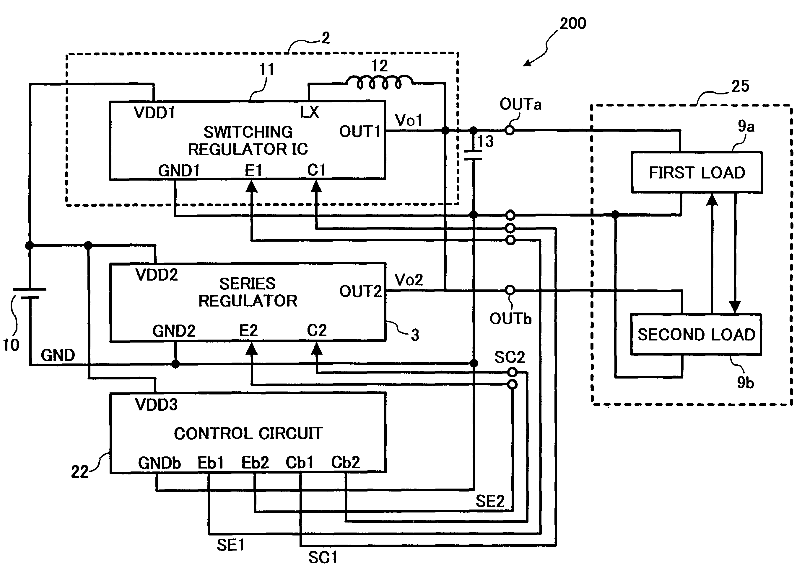
[0037]In describing preferred embodiments illustrated in the drawings, specific terminology is employed for the sake of clarity. However, the disclosure of this patent specification is not intended to be limited to the specific terminology so selected and it is to be understood that each specific element includes all technical equivalents that operate in a similar manner. Referring now to the drawings, wherein like reference numerals designate identical or corresponding parts throughout the several views, particularly to FIG. 3, a power supply apparatus 1 according to a preferred embodiment of the present invention is now described.

[0038]As shown in FIG. 3, the power supply apparatus 1 includes a switching regulator 2, series regulator 3, and control circuit 4. The switching regulator 2 and the series regulator 3 are step-down regulators that switch output voltage values when predetermined signals are input. The control circuit 4 controls the switching regulator 2 and the series reg...


PUM


Abstract

A power supply apparatus includes a switching regulator, a series regulator, and a controller. The switching regulator performs start and stop operations in response to a first control signal and generates a first constant voltage in response to a first voltage switching signal to output the second constant voltage. The series regulator performs start and stop operations in response to a second control signal and generates a second constant voltage in response to a second voltage switching signal to output the second constant voltage. The controller generates the first and second control signals and the first and second voltage switching signals and controls the switching regulator and the series regulator to simultaneously operate for at least a predetermined time period using the first and second control signals, respectively, and such that an output voltage of the switching regulator is greater than an output voltage of the series regulator.

Description

[0001]This application is a divisional of application No. 10 / 645,603, filed on Aug. 22, 2003, which now U.S. Pat. No. 7,129,681 is based on Japanese patent application No. 2002-244232 filed on Aug. 23, 2002 in the Japanese Patent Office, which are hereby incorporated by reference in their entireties.FIELD OF THE INVENTION[0002]The prevent invention relates to power supply apparatuses for use in apparatuses employing a battery such as e.g., cellular phones and more particularly to a power supply apparatus and its method for reducing power consumption.BACKGROUND OF THE INVENTION[0003]Recently, there has been a trend toward power consumption reduction of electrical appliances, particularly with battery-operated apparatuses depending on environmental concerns. Generally, means for power consumption reduction requires two important things. One is to reduce power consumed by electrical appliances. The other is to improve efficiency of the power supply itself and minimize wasteful power co...

Claims


Application Information

Patent Timeline
Patent Type & Authority Patents(United States)
IPC IPC(8): H02J1/00G05F1/56H02J7/00H02M3/155H02M3/158
CPCH02J7/0065H02M3/1584H02M2001/0045H02J2207/20H02M1/0045
Inventor FUJII, TATSUYA
Owner RICOH ELECTRONIC DEVICES CO LTD
Why Eureka
Try Eureka