Switch circuitry for a fluid monitoring device

a fluid monitoring and switch circuit technology, applied in the field of switch circuitry for fluid monitoring devices, can solve the problems of reducing the power consumption affecting the operation of the fluid monitoring device, and consuming little or no power of the fluid monitoring unit, so as to reduce the overall power consumption of the electronics and efficiently manage the power consumption

Pending Publication Date: 2021-12-30
KONINKLJIJKE PHILIPS NV
View PDF2 Cites 0 Cited by
  • Summary
  • Abstract
  • Description
  • Claims
  • Application Information

AI Technical Summary

Benefits of technology

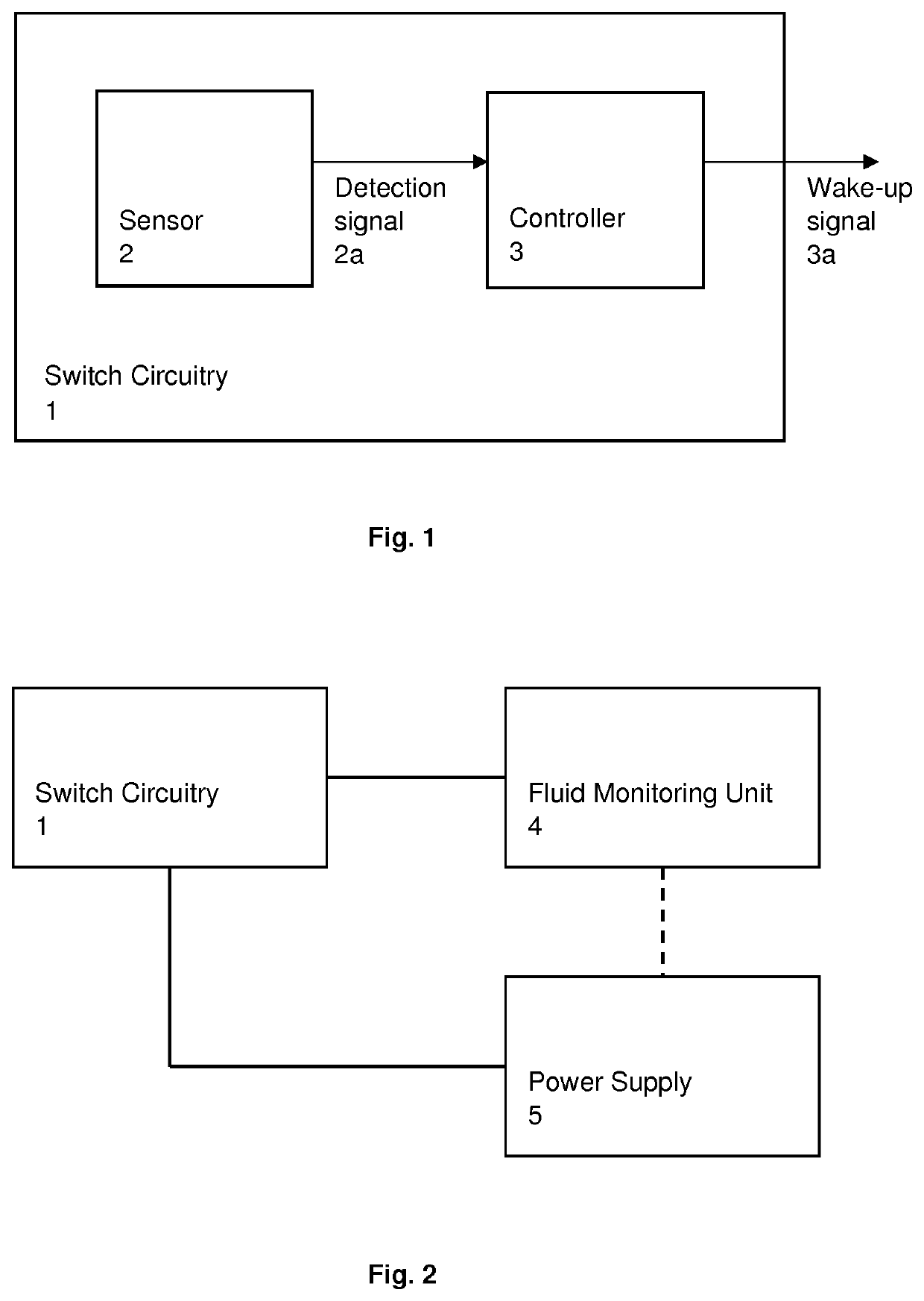
[0008]The power consumption of the fluid monitoring unit may therefore be reduced and limited to occasions when bodily fluids derived from the skin of the user, such as sweat, is present. That is, at times when there is no fluid present, there is nothing for the fluid monitoring unit to measure / monitor and so there is no need for the fluid monitoring unit to be active and power consumed by the unit will be wasted. Thus, by controlling the power supplied to the fluid monitoring unit in accordance with the detection of fluid, the power consumption of the unit may be appropriately limited and the lifespan of the power source, for example, a battery, may be maximised.
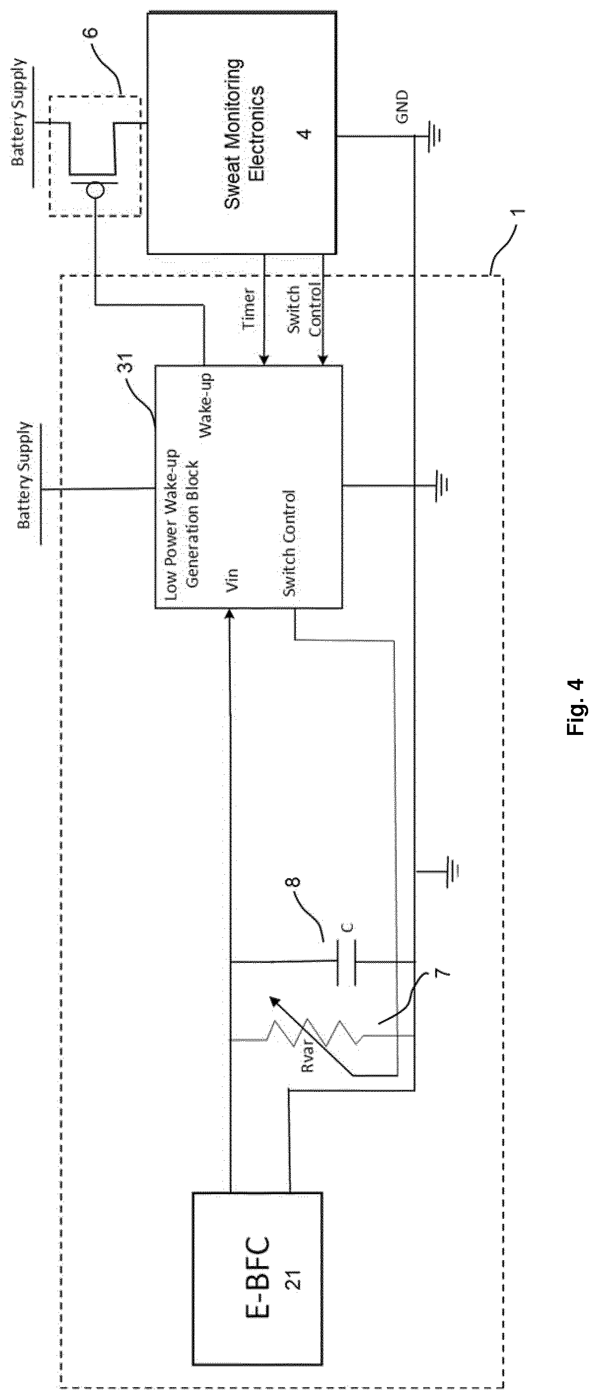
[0046]It may therefore be seen that embodiments of the present invention may provide means for minimising the overall power consumption of the electronics and efficiently managing the power consumed by the fluid monitoring electronics in accordance with the detection of fluids derived from the skin of the user, such as sweat.

Problems solved by technology

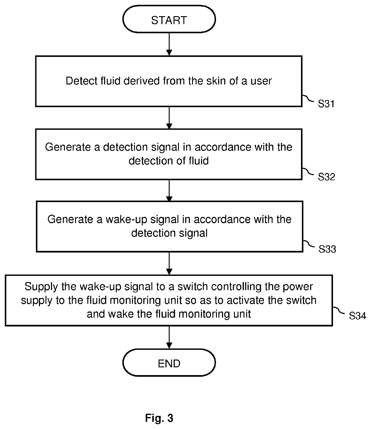
Conversely, power may not be supplied to the fluid monitoring unit when there is no fluid or an insufficient amount of fluid detected, and so the fluid monitoring unit may consume little or no power during periods when there is no fluid on which to perform monitoring.
The power consumption of the fluid monitoring unit may therefore be reduced and limited to occasions when bodily fluids derived from the skin of the user, such as sweat, is present.

Method used


Image

  • Switch circuitry for a fluid monitoring device
  • Switch circuitry for a fluid monitoring device
  • Switch circuitry for a fluid monitoring device

Examples


Embodiment Construction

[0057]The embodiments of the present disclosure and the various features and advantageous details thereof are explained more fully with reference to the non-limiting examples that are described and / or illustrated in the drawings and detailed in the following description. It should be noted that the features illustrated in the drawings are not necessarily drawn to scale, and features of one embodiment may be employed with other embodiments as the skilled artisan would recognise, even if not explicitly stated herein. Descriptions of well-known components and processing techniques may be omitted so as to not unnecessarily obscure the embodiments of the present disclosure. The examples used herein are intended merely to facilitate an understanding of ways in which the embodiments of the present may be practiced and to further enable those of skill in the art to practice the same. Accordingly, the examples herein should not be construed as limiting the scope of the embodiments of the pre...


PUM


Abstract

According to an aspect, there is provided switch circuitry (1) for controlling power supplied to a fluid monitoring unit (4). The switch circuitry (1) comprises: a sensor (2) configured to detect fluid derived from the skin of a user and to generate a detection signal in response to detection of fluid; and a controller (3) configured to receive the detection signal, to generate a wake-up signal in accordance with the detection signal, and to supply the wake-up signal to a switch (6) controlling the power supply to the fluid monitoring unit (4) so as to activate the switch (6) and wake the fluid monitoring unit (4), wherein, optionally, the fluid is sweat. According to another aspect, there is provided method of controlling power to a fluid monitoring unit.

Description

FIELD OF THE INVENTION[0001]Embodiments of the present invention relate generally to controlling power supplied to a fluid monitoring device.BACKGROUND OF THE INVENTION[0002]Non-invasive, continuous and prolonged monitoring of biomarkers that indicate health and well-being is in demand. For example, for monitoring dehydration, stress, sleep, children's health and in perioperative monitoring. Bodily fluids derived from the skin, such as sweat, sebum and interstitial fluid, may be used in monitoring. For example, sweat is a non-obtrusively accessible bio-fluid containing physiologically and metabolically rich information. The development of reliable sweat sensing has been hampered by several issues: (1) results from sweat sensing have been highly variable; (2) a correlation between blood and sweat values appears to be lacking for various biomarkers; (3) the focus of sweat sensing has been on sensors, not on reliable and robust collection methods for the minute amounts produced. Some e...

Claims


Application Information

Patent Timeline
Patent Type & Authority Applications(United States)
IPC IPC(8): A61B5/304A61B5/145
CPCA61B5/304A61B5/14517A61B5/14507
Inventor VISWESWARA, ASHOKA SATHANURJOHNSON, MARK THOMASGERHARDT, LUTZ CHRISTIANVAN LIESHOUT, RON MARTINUS LAURENTIUS
Owner KONINKLJIJKE PHILIPS NV
Why Eureka
Try Eureka