Current collector having a built-in sealing means, bipolar battery including such a collector, method for manufacturing such a battery

a current collector and sealing means technology, applied in the field of lithiumion electrochemical generators, can solve the problems of bipolar battery malfunction, compartments that are perfectly leak-tight, and substantial risk of the sealing frame being subjected to very different stresses

Active Publication Date: 2019-12-03
COMMISSARIAT A LENERGIE ATOMIQUE ET AUX ENERGIES ALTERNATIVES
View PDF43 Cites 2 Cited by
  • Summary
  • Abstract
  • Description
  • Claims
  • Application Information

AI Technical Summary

Benefits of technology

[0037]To do this, one subject of the invention is a device for a lithium-ion electrochemical generator, of elongate shape along a longitudinal axis X, comprising a band comprising a central portion, which is at least electrically conductive in part, forming a current collector at least one of the two main faces of which is covered with an electrode made of a lithium-ion insertion material, and at least two lateral peripheral portions connected to the central portion and extending transversely to the longitudinal axis, the lateral peripheral portions being made of an electrically insulating material comprising at least one polymer, the insulating material of at least one of the two lateral portions being able to be elastically or plastically deformed, the dimensions of said one of the two lateral portions furthermore being defined to allow its deformation without rupture during a coiling of the band around a coiling axis Y that is transverse to the longitudinal axis X and in proximity to the other of the two lateral peripheral portions.
[0038]According to the invention, a current collector carrier band is produced at least one sealing portion of which is elastically or plastically deformable in order to be able to undergo the tensile stresses during the winding without there being any risk of the seal tightness to the electrolyte decreasing. The dimension of the deformable portion made of polymer in the coiling direction, i.e. in the direction of the longitudinal axis X, is advantageously chosen depending on the number of stacked compartments that form in the end the bipolar battery once the winding has been carried out. The larger the number of stacked compartments to be wound, the greater the radius of curvature (and therefore the stretching) of the outermost carrier band of the current collector of the coil, i.e. of the collector that is initially located on top of the stack. In other words, before the coiling (winding) is carried out a dimension is determined for the deformable part, said dimension being large enough that the part is able to undergo the tensile stresses during the winding without running the risk of rupturing.
[0043]Thus, the device according to the invention makes it possible to preserve the actual seal tightness of a bipolar battery during its winding. It is therefore possible to envision using for high powers bipolar batteries integrating by winding devices according to the invention in an accommodating volume up to now dedicated to the accommodation of monopolar batteries.
[0050]According to another embodiment, the band itself may be made of an electrically insulating material that is able to be deformed, the electrically conductive part then consisting of electrically conductive particles embedded in the band. The conductive particles may be carbon particles, metal beads, etc. Care will of course be taken to ensure that the electrically conductive particles connect the two faces of a current collector. The addition of conductive particles has the effect of strengthening the polymer of the band and of making it impossible or very difficult to deform in the active zone of the electrodes.
[0051]According to this other embodiment, the band is mechanically reinforced at its periphery, except for the lateral portion dimensioned for its deformation, by non-conductive electrical particles. Thus, it is possible to increase the rigidity of the electrically insulating band in the locations where the deformation is not desired during the winding.
[0076]The process for producing by winding into a coil a high-capacity bipolar battery according to the invention is particularly advantageous since it makes it possible to coil (wind) all the compartments of the battery as though there were only one single thickness to be wound and without running the risk of decreasing the seal tightness of the battery.

Problems solved by technology

The main difficulty with designing a bipolar battery is the production of compartments that are perfectly leak-tight to the electrolyte, in general a liquid, one with respect to the others.
Specifically, a poor seal tightness leads to ionic short-circuits that cause the bipolar battery to malfunction.
This means that there is a substantial risk of the sealing frame being subjected to very different stresses, and therefore a risk of rupture zones being created.
Thus, it is not possible to envision winding a bipolar battery comprising stacked bipolar compartments while preserving the seal tightness thereof obtained beforehand using a peripheral sealing frame such as described in patent U.S. Pat. No. 6,664,006.
This solution has the major drawback that the area of the collector-bearing metal carrier to be employed is large relative to the active area dedicated to the electrodes.
Furthermore, production of a plurality of bipolar elements on a given current-collector carrier may prove to be tricky because of the fragility of the carrier during the procedure.

Method used


Image

  • Current collector having a built-in sealing means, bipolar battery including such a collector, method for manufacturing such a battery
  • Current collector having a built-in sealing means, bipolar battery including such a collector, method for manufacturing such a battery
  • Current collector having a built-in sealing means, bipolar battery including such a collector, method for manufacturing such a battery

Examples


first embodiment

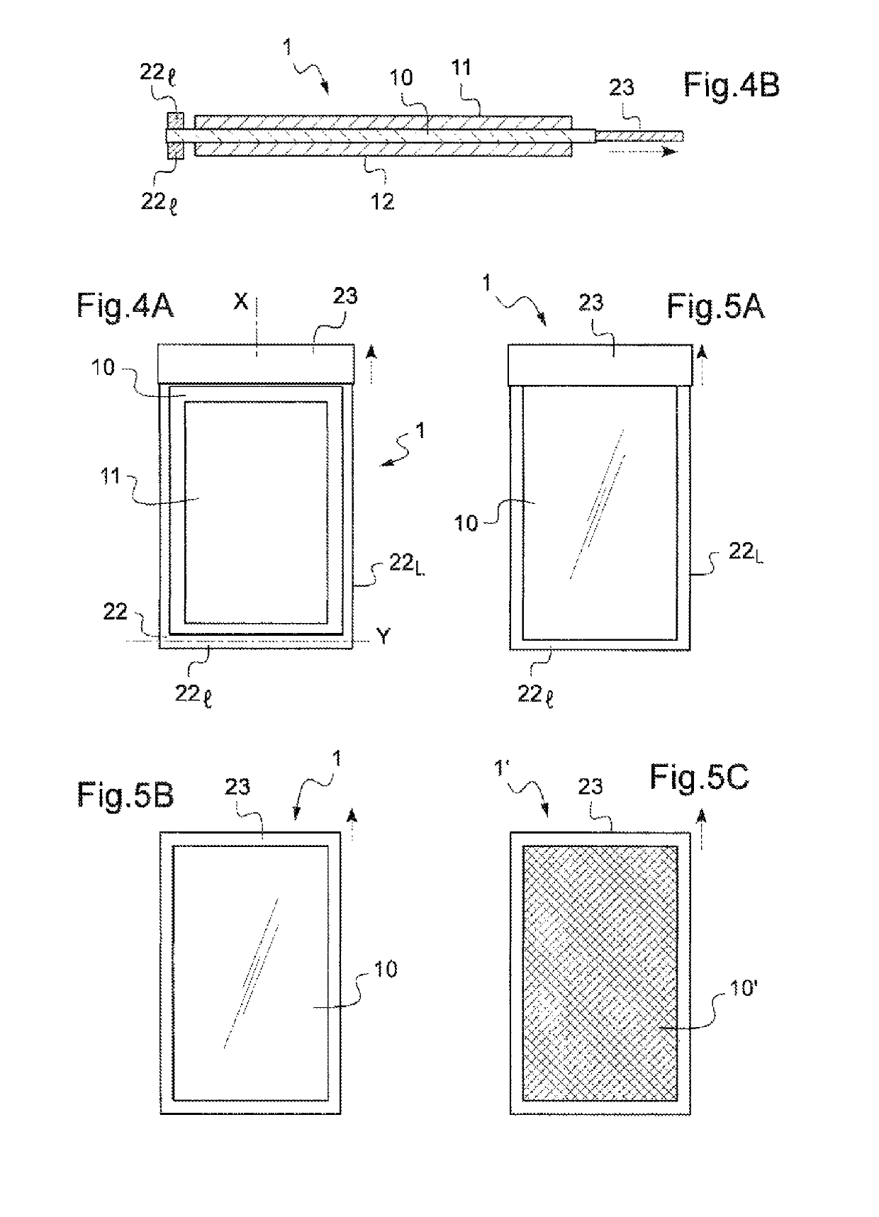
[0120] the central portion 10 may consist of a metal sheet, typically made of aluminum as shown in FIGS. 4A and 4B. The lateral portion 23 according to the invention is then sealed, and may then either be welded, or adhesively bonded or heat sealed to the metal sheet.

[0121]The metal sheet 10 may be sealed to a frame made of an electrically insulating material 22 having a U-shape as seen from in front, which encircles said sheet except for the lateral portion 23 dimensioned for its deformation. Thus, as shown in FIGS. 4A, 4B and 5A, the U-shaped frame 22 comprises the lateral peripheral portion 221 and two longitudinal peripheral portions 22L. Eventually, all the peripheral portions 221, 22L of the frame 22 and the deformable portion 23 form one of the seal-tight walls of the bipolar battery.

[0122]Alternatively, the metal sheet 10 may be sealed to a single frame 23 made of an electrically insulating material that is able to be deformed, which frame 23 completely encircles said sheet ...

second embodiment

[0123] the band itself 1′ may consist of an electrically insulating material incorporating the deformable lateral portion 23, the conductive part 10′ then consisting of electrically conductive particles (FIG. 5C). The conductive particles may especially be carbon particles or metal beads, etc. Whatever the material, the shape and size of these particles 10′, care is taken that, when embedded in the band 1′, the conductive particles 10 connect the two main faces so as to ensure the electrical continuity between the latter. Although not shown, other variants may be provided: in particular, provision may be made to reinforce the polymer-based material of the band 1′ with electrically non-conductive particles, except for in the deformable peripheral portion 23.

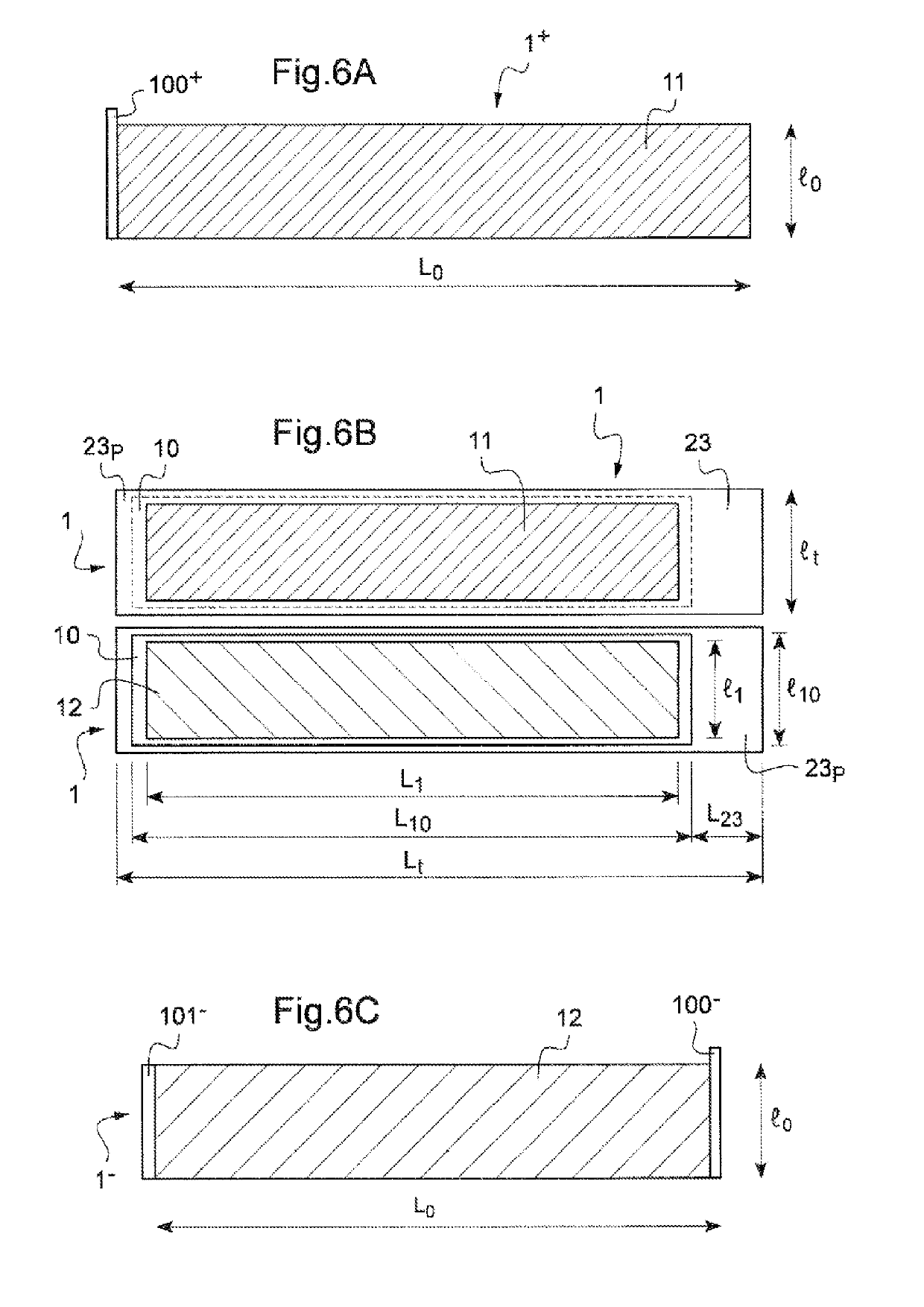
[0124]In FIGS. 6A to 9D, a process for producing by winding a bipolar battery according to the invention has been illustrated, each of the unitary devices 1 being produced according to the first embodiment, i.e. with a current col...


PUM

PropertyMeasurementUnit
thicknessaaaaaaaaaa
thicknessaaaaaaaaaa
thicknessaaaaaaaaaa

Abstract

The invention relates to a device for a lithium electrochemical generator, having an elongate shape along a longitudinal axis (X), comprising a strip comprising a current collector central portion that is at least partially electrically conductive, in which at least one of the two main surfaces is covered with an electrode consisting of a lithium insertion material, and at least two side peripheral portions connected to the central portion and extending transversely to the longitudinal axis, the side peripheral portions being made of an electrically insulating material comprising at least one polymer, the insulating material of at least one of the two side portions being resiliently or plastically deformable, the dimensions of the latter also being determined such as to allow the deformation thereof without breaking during the winding of the strip about a winding axis, which is transverse to the axis (X) and adjacent to the other one of the two side peripheral portions. The invention relates to the method for manufacturing a related bipolar battery.

Description

CROSS-REFERENCE TO RELATED APPLICATIONS[0001]This application is a national phase application under 35 U.S.C. § 371 of International Application No. PCT / IB2013 / 059015 filed 30 Sep. 2013, which claims priority to French Patent Application No. 12 59260 filed 1 Oct. 2012. The entire contents of each of the above-referenced disclosures is specifically incorporated herein by reference without disclaimer.TECHNICAL FIELD[0002]The present invention relates to the field of lithium-ion electrochemical generators, which function according to the principle of insertion or deinsertion, or in other words intercalation / deintercalation, of lithium ions in at least one electrode.[0003]It more particularly relates to a lithium-ion electrochemical accumulator comprising at least one bipolar current collector, also referred to as a bipolar battery. In such a bipolar battery, the bipolar collector bears on each of its opposite faces one of two oppositely signed electrode materials, i.e. a cathode (posit...

Claims


Application Information

Patent Timeline
Patent Type & Authority Patents(United States)
IPC IPC(8): H01M4/70H01M10/0525H01M4/13H01M4/139H01M4/75H01M10/052H01M10/0587H01M4/66H01M10/04H01M4/02
CPCH01M4/70H01M10/0587H01M4/75H01M10/052H01M10/0431H01M4/13H01M4/66H01M10/0525H01M4/139H01M10/044H01M2004/029Y10T29/4911Y02E60/10Y02P70/50
Inventor CHAMI, MARIANNEREYNIER, YVAN
Owner COMMISSARIAT A LENERGIE ATOMIQUE ET AUX ENERGIES ALTERNATIVES
Why Eureka
Try Eureka