
Cable plugs for bone plates

a technology of bone plate and cable plug, which is applied in the field of systems, can solve the problems of bone plate shifting relative to the bone, system failure to provide a means of orienting surgical cable, and insufficient elimination of stresses, so as to facilitate the engagement of cable plug and enhance the flexibility and resiliency of cable plug

Active Publication Date: 2019-12-10
STRYKER EURO OPERATIONS HLDG LLC
View PDF213 Cites 1 Cited by
  • Summary
  • Abstract
  • Description
  • Claims
  • Application Information

AI Technical Summary

Benefits of technology

The patent describes a cable plug that has an aperture for inserting a cable wire and an interior conduit that connects to the aperture. The plug is designed to be flexible and resilient, allowing for easy engagement with a bone plate. The technical effects of the design include improved flexibility, durability, and ease of use.

Problems solved by technology

This may result in shear stresses and strains in the surgical cable that cause the bone plate to shift relative to the bone.
These systems do not, however, provide a means of orienting the surgical cable at an angle less than 90° from the longitudinal axis of the bone.
Therefore, they cannot sufficiently eliminate the stresses and strains in the surgical cable which may cause shifting of the bone plate.

Method used


Image

  • Cable plugs for bone plates
  • Cable plugs for bone plates
  • Cable plugs for bone plates

Examples


Embodiment Construction

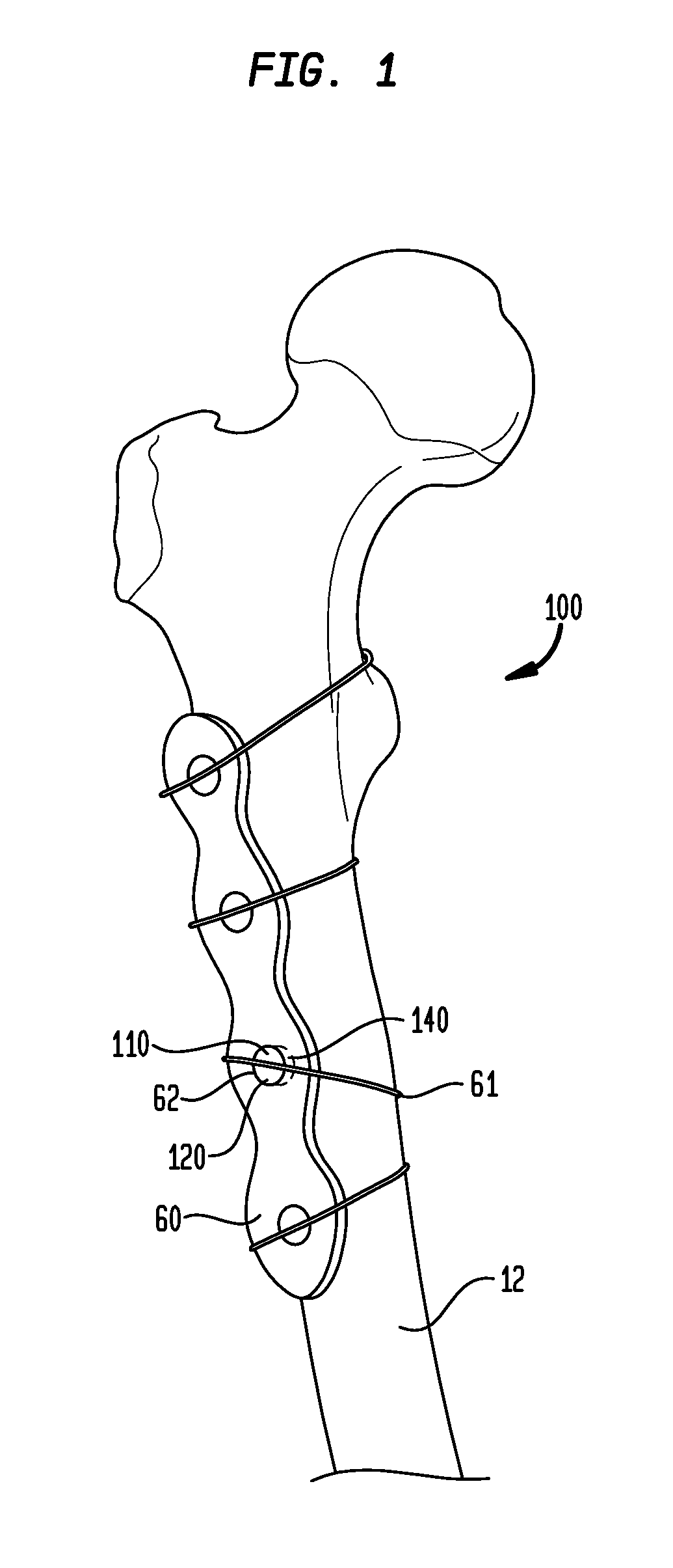
[0088]Although the embodiments described below and shown in the figures are described with reference to specific embodiments of the present cable plug invention, it is to be understood that the concepts and novelty underlying the present invention could be utilized for any type of medical procedure requiring bone attachment. Moreover, although described in connection with the bone attachment, it is contemplated that the present invention may be used to fix a variety of devices to a variety of surfaces, such as the surface of a synthetic bone or implant.

[0089]As used herein, when referring to bones or other parts of the body, the term “proximal” means closer to the heart; “distal” means more distant from the heart; “inferior” means toward the feet; “superior” means towards the head; “anterior” means towards the front part of the body or the face; “posterior” means towards the back of the body; “medial” means toward the midline of the body; and “lateral” means away from the midline of...


PUM


Abstract

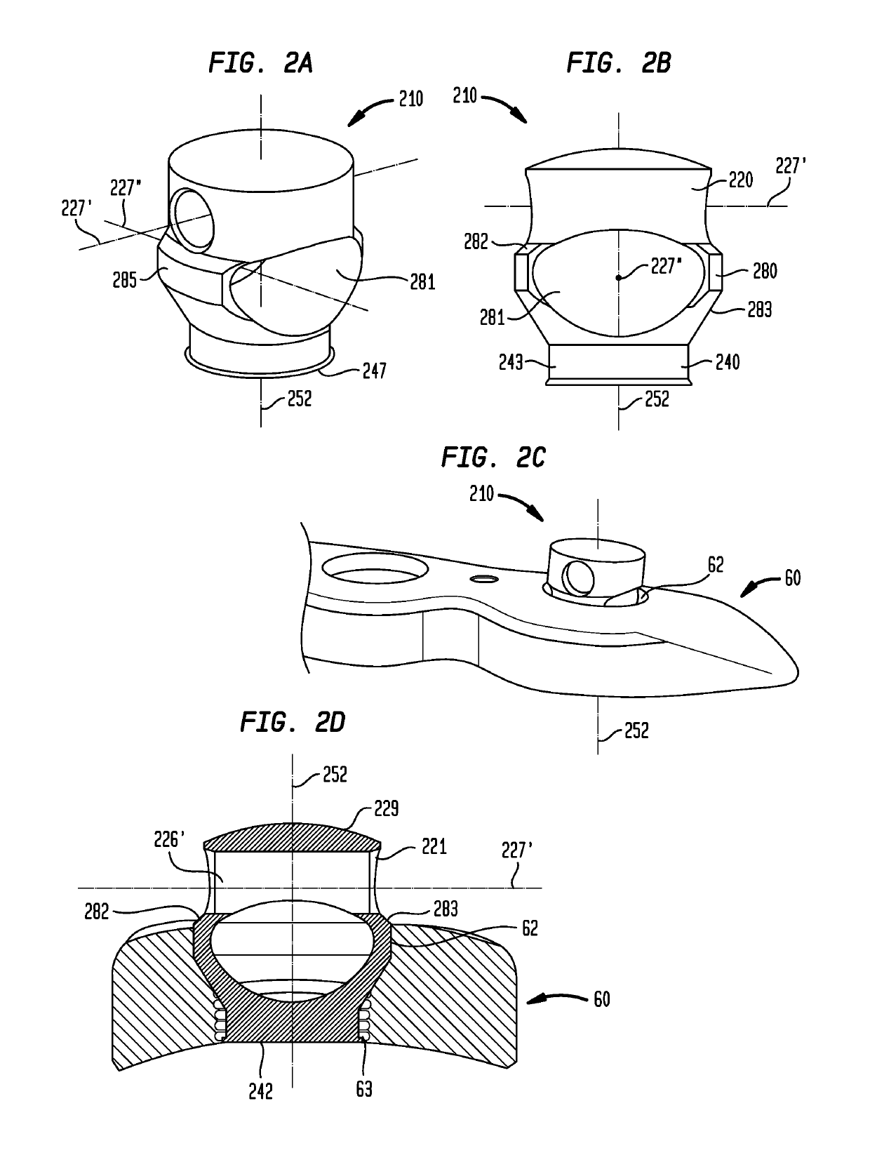
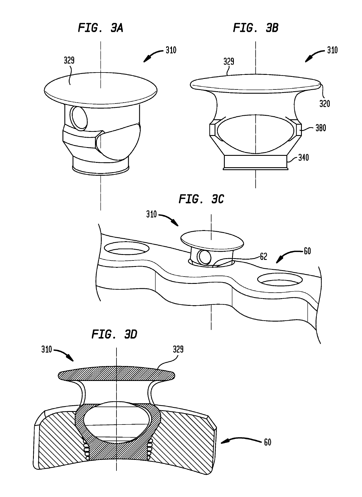
Various embodiments of a cable plug and a cable wire attachment plate are disclosed herein. Each plug or plate has a cable retaining portion and a fastening portion disposed from the cable retaining portion about a longitudinal axis of the plug or plate. Each cable retaining portion preferably has an aperture or channel for receiving a cable wire therein, while each fastening portion is adapted to engage a portion of a bone plate, such as a hole in the bone plate or an exterior surface of the bone plate. Related methods, systems, and kits are also disclosed.

Description

CROSS-REFERENCE TO RELATED APPLICATIONS[0001]The present application claims priority from provisional U.S. Patent Application Ser. No. 62 / 093,127, filed Dec. 17, 2014, and provisional U.S. Patent Application Ser. No. 62 / 035,074, filed Aug. 8, 2014, both of which are incorporated herein by reference.FIELD OF THE INVENTION[0002]The present invention relates to systems for coupling surgical cables to bone plates when reducing bone fractures or repairing fractured bones. More particularly, the invention relates to systems that utilize a cable plug or a cable attachment plate, affixed to a bone plate, to receive and retain a surgical cable. In some embodiments, the surgical cable may be oriented with respect to the bone at a plurality of angles relative to the longitudinal axis of the bone.BACKGROUND OF THE INVENTION[0003]Surgical cables are used in many surgical procedures. They are generally used to encircle the bone alone, or the bone and a bone plate, to facilitate fixation of one or...

Claims


Application Information

Patent Timeline
Patent Type & Authority Patents(United States)
IPC IPC(8): A61B17/82A61B17/84A61B17/88A61B17/80
CPCA61B17/8861A61B17/842A61B17/82A61B17/80
Inventor WIEDERKEHR, ANDREASSYLVESTRE, PIERRE-LUC
Owner STRYKER EURO OPERATIONS HLDG LLC
Learn More