Retraction device and pull-out guide

Active Publication Date: 2019-12-24
PAUL HETTICH
View PDF15 Cites 0 Cited by
  • Summary
  • Abstract
  • Description
  • Claims
  • Application Information

AI Technical Summary

Benefits of technology

[0016]Preferably, a middle rail is arranged between the guide rail and the running rail, the middle rail being shorter than the running rail or the guide rail,

Problems solved by technology

This results in a particularly compact construction, as the damper

Method used


Image

  • Retraction device and pull-out guide
  • Retraction device and pull-out guide
  • Retraction device and pull-out guide

Examples


Example

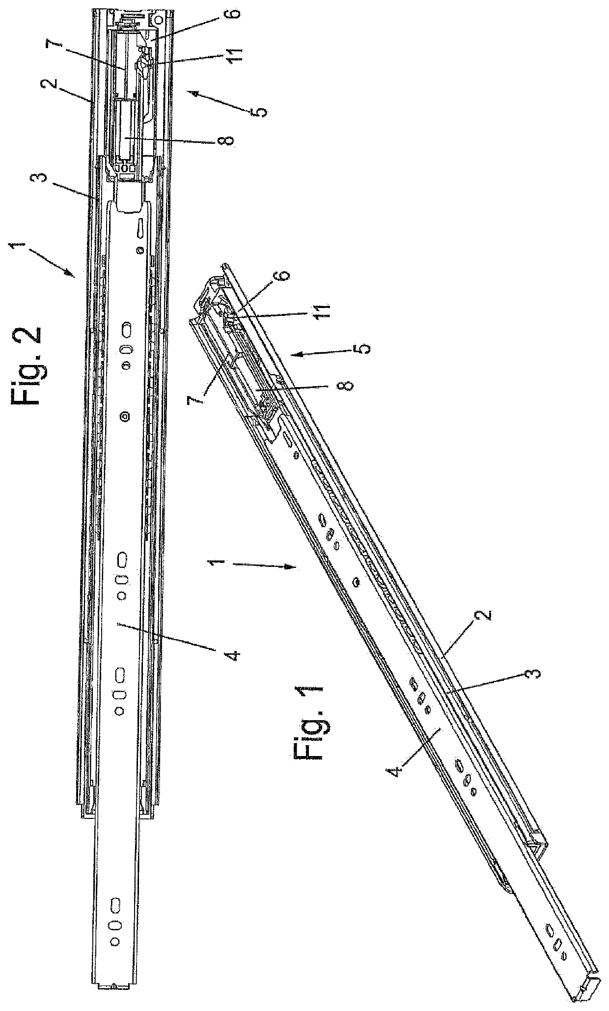
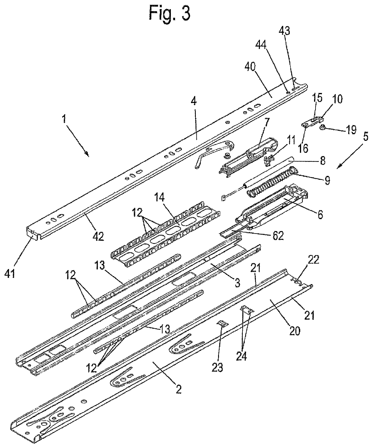
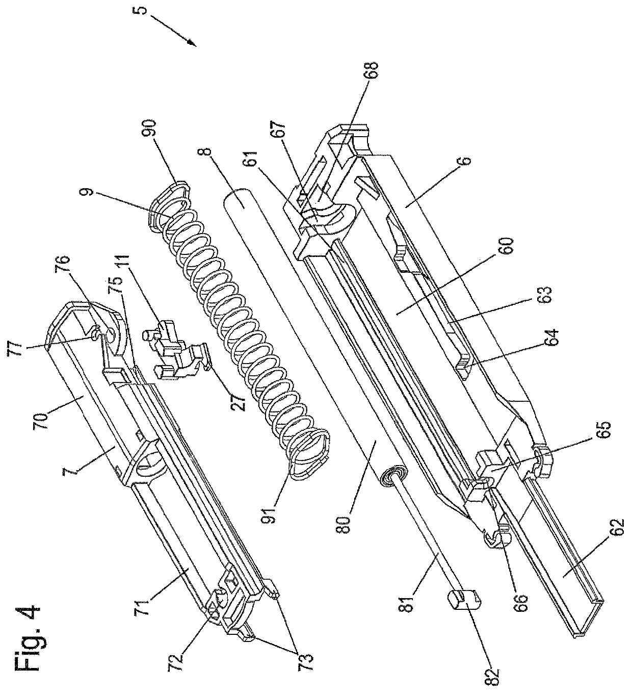
[0035]A pull-out guide 1 comprising a stationary guide rail 2, which can be fixed on a furniture body, a middle rail 3 and a running rail 4. The middle rail 3 is arranged between the guide rail 2 and the running rail 4 and is shorter than the other two. In extension of the middle rail 3, a retraction device 5 is provided which is fixed on the guide rail 2 together with a housing 6. The retraction device 5 comprises a movable slider 7, which is connected to a driver 11. The slider 7 is pretensioned in a retracted position by means of a spring 9 and further coupled with a damper 8, in order to slow down the running rail 4 upon its closing movement before reaching its closed position, in order to prevent loud impact noises.

[0036]As shown in FIG. 3, the guide rail 2, the middle rail 3 and the running rail 4 are C- or U-shaped in cross-section. The guide rail 2 has a bottom 20, from which two legs 21 protrude, having running tracks for bearing elements 12. The ball shaped bearing element...


PUM


Abstract

A retraction device, in particular for pull-out guides, has a housing, in which a guide for a linearly movable slider and a guide track for a driver attached to the slider are provided. The driver can be coupled with an activator and a damper comprising a damper housing and a piston rod is provided between the housing and the slider. There is a pull-out guide with a stationary guide rail and a running rail which is movable relative to the guide rail.

Description

CROSS REFERENCE TO RELATED APPLICATIONS[0001]This application is the National Stage of PCT / EP2017 / 055706 filed on Mar. 10, 2017, which claims priority under 35 U.S.C. § 119 of Chinese Application No. 201610150855.1 filed on Mar. 16, 2016 and German Application No. 10 2016 105 100.4 filed on Mar. 18, 2016, the disclosures of which are incorporated by reference. The international application under PCT article 21(2) was not published in English.BACKGROUND OF THE INVENTION[0002]The present invention relates to a retraction device, in particular for pull-out guides, comprising a housing, in which a guide for a linearly movable slider and a guide track for a driver attached to the slider are provided, wherein the driver can be coupled with an activator and a damper comprising a damper housing and a piston rod is provided between the housing and the slider, and a pull-out guide with a stationary guide rail and a running rail which is movable relative to the guide rail.[0003]U.S. Pat. No. 6...

Claims


Application Information

Patent Timeline
IPC IPC(8): A47B88/467A47B88/487A47B88/477E05F3/10
CPCA47B88/467A47B88/487A47B88/477E05F3/108E05Y2900/20E05F1/16E05F5/027E05Y2201/10E05Y2201/684E05Y2800/24
Inventor PAN, FORESTZENG, BODEWANG, FEMMYCHEN, ROYRUEDE, KAI-UWE
Owner PAUL HETTICH
Why Eureka
Try Eureka