Emergency detachable pipe coupling

a detachable pipe and coupling technology, applied in the direction of couplings, pipe couplings, liquid transfer devices, etc., can solve the problems of inability to decouple the pipe coupling, the tensile direction of the pipe coupling along the longitudinal axis direction may not be so great, and the above-described conventional emergency detachable pipe coupling is disadvantageous, so as to achieve the effect of reducing the urging force of the urging member

Active Publication Date: 2019-12-24
NITTO KOHKI CO LTD
View PDF11 Cites 6 Cited by
  • Summary
  • Abstract
  • Description
  • Claims
  • Application Information

AI Technical Summary

Benefits of technology

[0006]In the emergency detachable pipe coupling, when pipings which are connected to the female and male coupling members, respectively, are bent relative to each other and consequently high bending stress is applied to the pipings and the pipe coupling, for example, the male coupling member is tilted relative to the female coupling member, and the female coupling member and the male coupling member become decouplable and are thus detached from each other. Therefore, it is possible to prevent breakage of the pipings and devices connected thereto due to the high bending stress.
[0029]The auxiliary sleeve acts to resist tilting of the male coupling member relative to the female coupling member, in cooperation with the urging member acting to resist the tilting. Accordingly, the urging force of the urging member can be reduced as compared to a structure in which the urging member resists the tilting by itself.

Problems solved by technology

Accordingly, when excessive tensile force is, for some reason, applied to piping connected to the pipe coupling, the piping or a device connected to the piping, for example, may be broken, which may cause an unexpected accident.
The above-described conventional emergency detachable pipe coupling is disadvantageous as will now be explained.
However, when pipings which are connected to the female and male coupling members, respectively, are bent relative to each other and hence high bending stress is applied to the pipings and the pipe coupling, for example, even if the bending stress is so high that the pipings or the pipe coupling may be broken, the force acting on the pipe coupling in the tensile direction along the longitudinal axis direction may not be so great, so that the pipe coupling may fail to be decoupled.

Method used


Image

  • Emergency detachable pipe coupling
  • Emergency detachable pipe coupling
  • Emergency detachable pipe coupling

Examples


Embodiment Construction

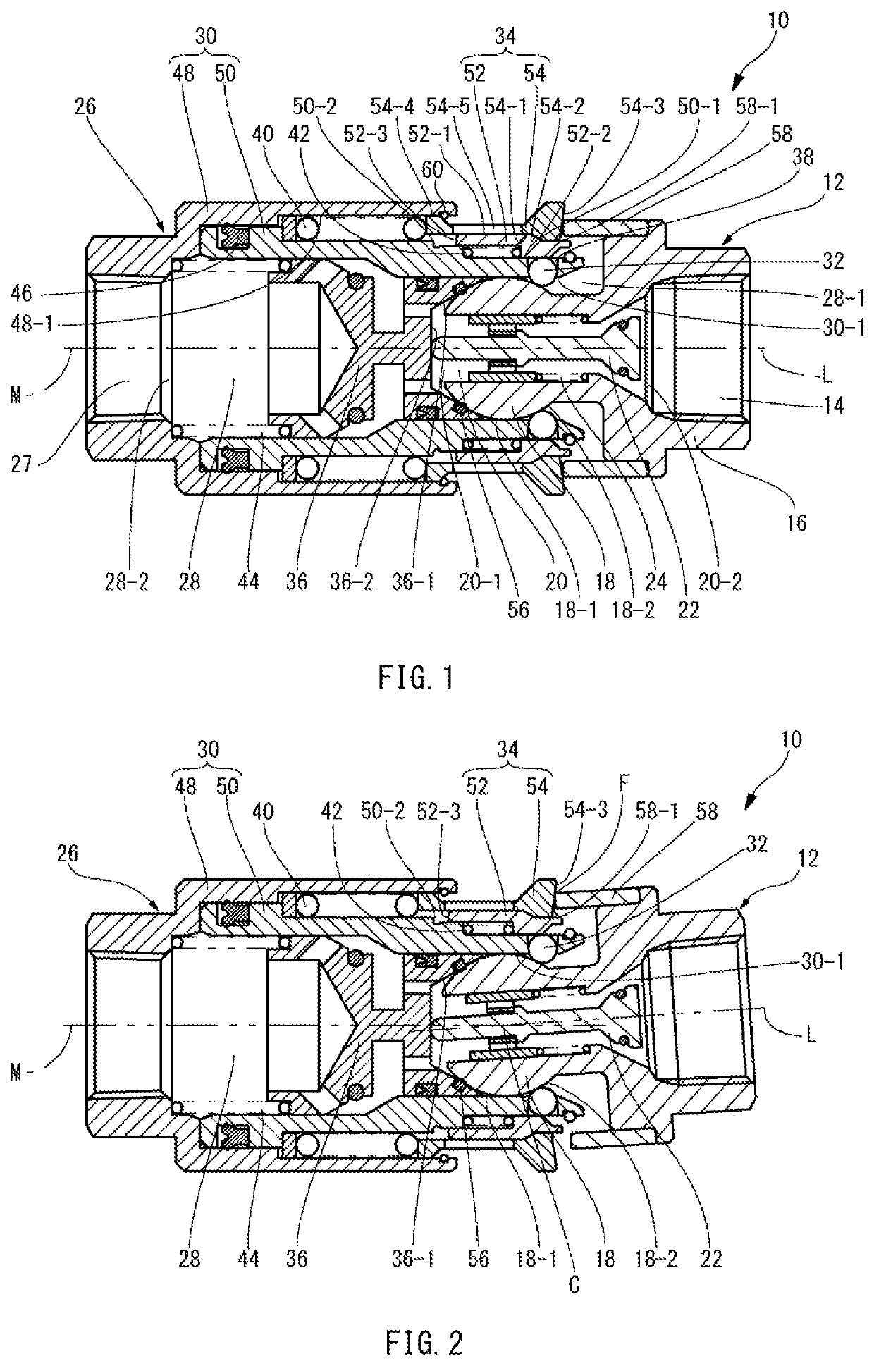
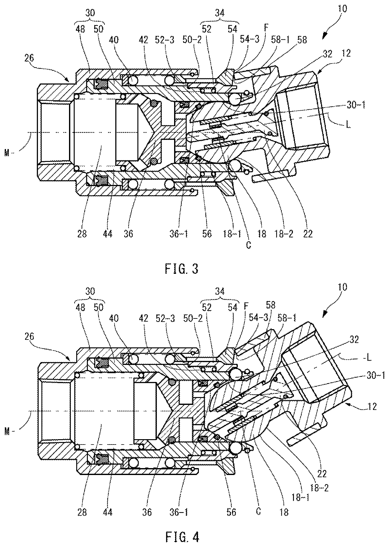
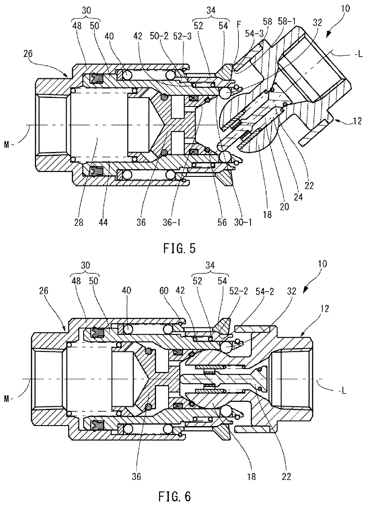
[0045]As shown in FIG. 1, an emergency detachable pipe coupling 10 according to a first embodiment of the present invention comprises a male coupling member 12 and a female coupling member 26 having the male coupling member 12 coupled thereto. In the coupled state, a connecting end portion 18 of the male coupling member 12 is locked in a female-side passage 28 of the female coupling member 26 by a locking element 32 so that the male coupling member 12 cannot be detached from the female coupling member 26. When the male coupling member 12 is tilted relative to the female coupling member 26 in the above-described coupled state, the restraint by the locking element 32 is cancelled so that the male coupling member 12 and the female coupling member 26 are decouplable from each other. The structure of the emergency detachable pipe coupling 10 will be explained below in detail.

[0046]The male coupling member 12 has a base portion 16 having a piping connecting portion 14, a connecting end po...


PUM


Abstract

An emergency detachable pipe coupling configured to decouple a female coupling member and a male coupling member which are coupled together when an external force makes the male coupling member tilted at a predetermined angle relative to a female coupling member. When the male coupling member is tilted, a pressing surface of the male coupling member presses a to-be-pressed surface of a locking element restraining member of the female coupling member to displace the locking element restraining member to a release position where a locking element becomes displaceable to an unlocking position.

Description

TECHNICAL FIELD[0001]The present invention relates to an emergency detachable pipe coupling configured to decouple a female coupling member and a male coupling member, which are in use being coupled together, when a force of a magnitude greater than a given magnitude acts thereon such that the female and male coupling members are tilted relative to each other.BACKGROUND ART[0002]In a conventional pipe coupling, a female coupling member and a male coupling member, when coupled together, are held with a locking element so as not to detach from each other. Accordingly, when excessive tensile force is, for some reason, applied to piping connected to the pipe coupling, the piping or a device connected to the piping, for example, may be broken, which may cause an unexpected accident. To prevent such an accident, there have been developed emergency detachable pipe couplings (Japanese Utility Model Registration Application Publication No. Hei 7-35893 and Japanese Patent No. 5,570,494 config...

Claims


Application Information

Patent Timeline
Patent Type & Authority Patents(United States)
IPC IPC(8): F16L37/23F16L37/32
CPCF16L37/32F16L37/23F16L2201/20F16L37/52F16L55/1015B67D7/3218
Inventor WADA, AKIHIRO
Owner NITTO KOHKI CO LTD
Why Eureka
Try Eureka