
Electronic circuitry for controlling in order to perform exposure measurements continuously, spectrometer using the same and measurement method of the spectrometer

a technology of spectrometer and electronic circuit, which is applied in the direction of optical radiation measurement, image enhancement, instruments, etc., can solve the problems of long wait required for existing spectral measurements, unstable, and easy failure of conventional spectrometers to obtain sufficient valid spectral data

Active Publication Date: 2019-12-24
OTO PHOTONICS
View PDF19 Cites 0 Cited by
  • Summary
  • Abstract
  • Description
  • Claims
  • Application Information

AI Technical Summary

Benefits of technology

[0005]The present invention provides an electronic circuitry of a spectrometer that enables the spectrometer to continuously perform multiple exposure measurements.
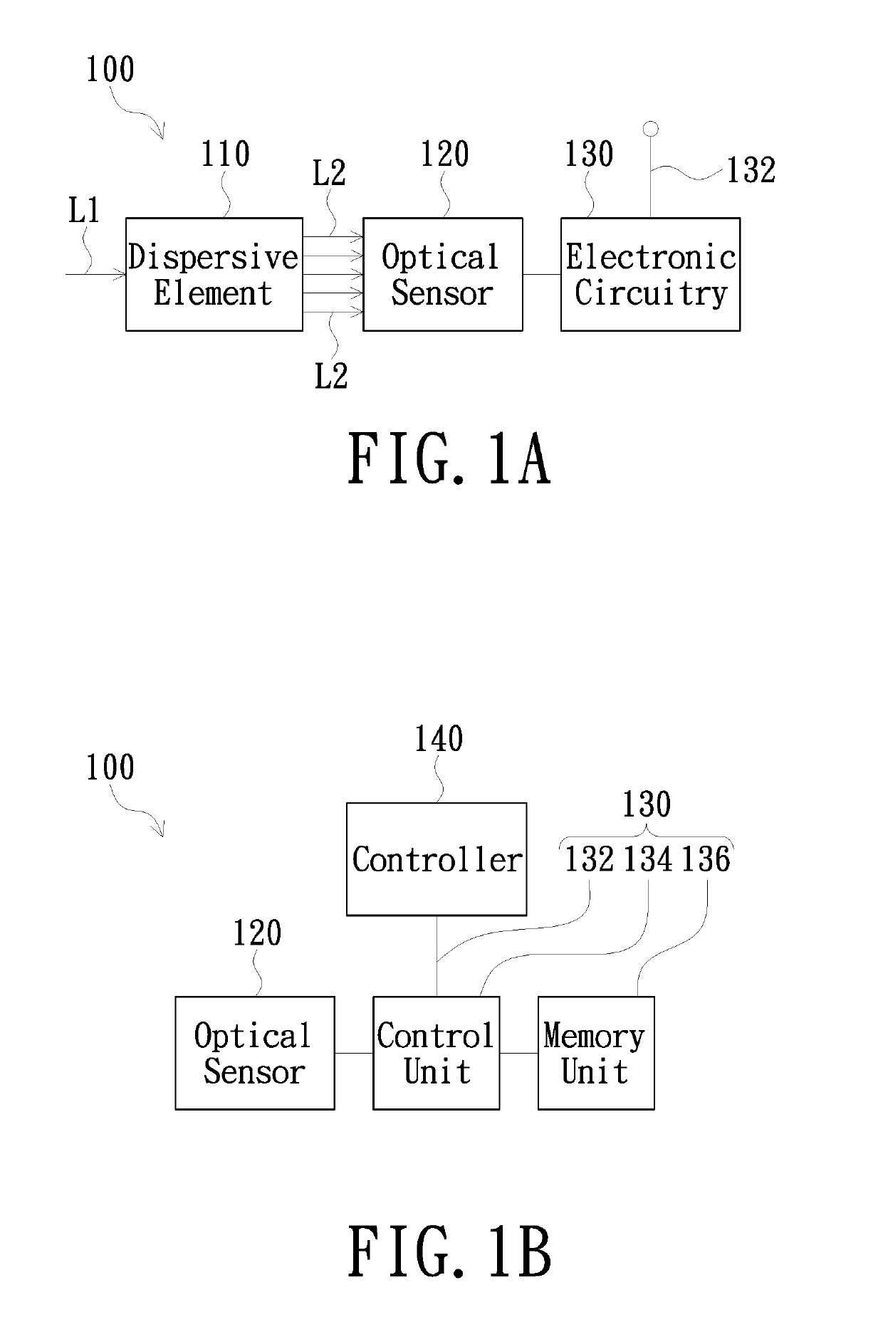
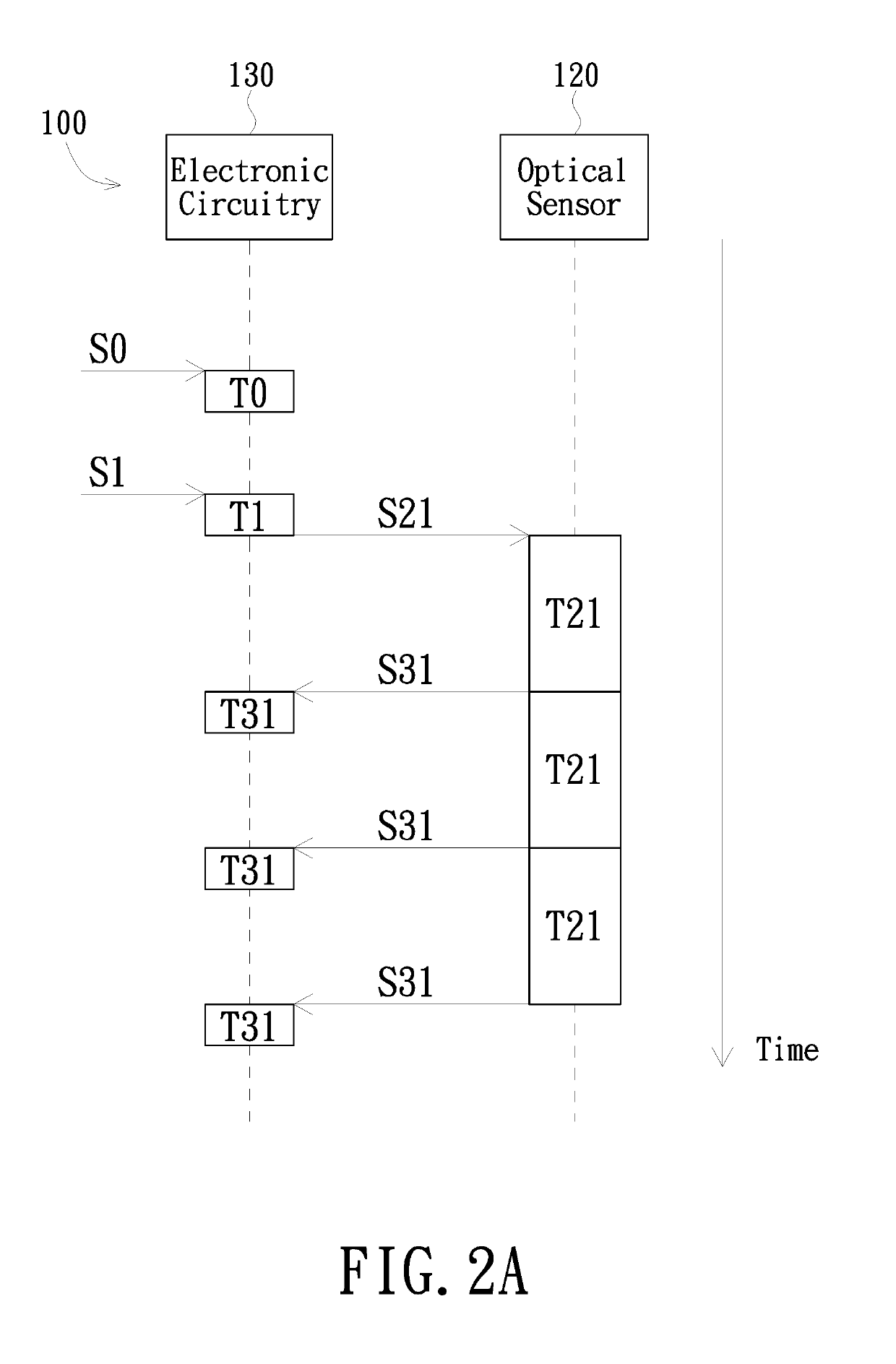
[0008]According to an embodiment of the present invention, an electronic circuitry of a spectrometer is configured to electrically connect with an optical sensor of the spectrometer. The electronic circuitry includes a memory unit, a trigger line, and a control unit. The memory unit is configured to store a measurement setting. The trigger line is configured to transmit at least one trigger signal. The control unit is electrically connected to the trigger line and the memory unit, and is configured to receive the trigger signal from the trigger line so as to instruct the spectrometer to perform a plurality of exposure measurements continuously under the measurement setting, and to save a plurality of spectral data acquired from the exposure measurements into the memory unit.
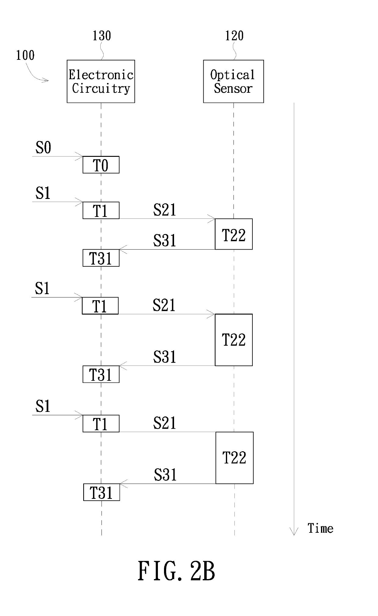
[0010]According to yet another embodiment of the present invention, a measurement method of a spectrometer includes: receiving at least one trigger signal from a trigger line; instructing the spectrometer to perform a plurality of exposure measurements continuously under a measurement setting stored in a memory unit according to the at least one trigger signal; and saving a plurality of spectral data acquired from the exposure measurements into the memory unit.
[0011]In sum, the electronic circuitry according to the embodiments of the present invention utilizes the memory unit to save the plurality of spectral data directly from the spectrometer, therefore allowing the spectrometer to perform multiple exposure measurements continuously without having to pause between measurements for transmission of spectral data to a processing device. Therefore, the spectrometer according to the embodiments of the present invention can continuously expose and measure within a limited time frame, and is thus advantageous in acquiring sufficient amounts of valid spectral data for analysis of reaction intermediates or other special substances or objects.

Problems solved by technology

Such spectral measurement has been disadvantageous in measuring unstable and short-lived substances, such as reaction intermediates, which require multiple exposure measurements to be performed within a very limited time frame to obtain sufficient amounts of spectral data for analysis of such intermediates.
The wait required in existing spectral measurements are generally long and unstable, and could vary by the speed of data transmission between the spectrometer and the computer.
Therefore, the conventional spectrometer may be easy to fail to obtain sufficient amounts of valid spectral data within a limited time frame.

Method used


Image

  • Electronic circuitry for controlling in order to perform exposure measurements continuously, spectrometer using the same and measurement method of the spectrometer
  • Electronic circuitry for controlling in order to perform exposure measurements continuously, spectrometer using the same and measurement method of the spectrometer
  • Electronic circuitry for controlling in order to perform exposure measurements continuously, spectrometer using the same and measurement method of the spectrometer

Examples


Embodiment Construction

[0020]The present invention will now be described more specifically with reference to the following embodiments. It is to be noted that the following descriptions of embodiments of this invention are presented herein for purpose of illustration and description only. It is not intended to be exhaustive or to be limited to the precise form disclosed.

[0021]Referring now to FIG. 1A. Spectrometer 100 according to an embodiment of the present invention includes a dispersive element 110, an optical sensor 120 and an electronic circuitry 130. The dispersive element 110 may separate an incident light L1 by diffraction, refraction or filtering into a plurality of spectral rays L2 of different wavelengths. The dispersive element 110 may be a transmissive grating, a reflective grating, a prism, or a filter array. The filter array may be a plurality of filters that are linearly aligned or arranged into a two-dimensional array.

[0022]The optical sensor 120 is configured to receive the spectral ray...


PUM


Abstract

An electronic circuitry of a spectrometer, configured to electrically connect with an optical sensor of the spectrometer, includes a memory unit configured to store a measurement setting, a trigger line configured to transmit at least one trigger signal, and a control unit electrically connected to the trigger line and the memory unit. The control unit is configured to receive the trigger signal from the trigger line so as to instruct the spectrometer to perform a plurality of exposure measurements continuously under the measurement setting, and to save a plurality of spectral data acquired from the exposure measurements into the memory unit. A spectrometer using the electronic circuitry for performing the exposure measurements and a measuring method of the spectrometer are also provided.

Description

FIELD OF THE INVENTION[0001]The present invention relates to an electronic circuitry of an optical measurement apparatus, and more particularly to an electronic circuitry of a spectrometer, the spectrometer using the electronic circuitry, and the measurement method of the spectrometer.BACKGROUND OF THE INVENTION[0002]In a spectral measurement according the prior art, a computer connected to a spectrometer would send an instruction to the spectrometer. The spectrometer would then perform an exposure according to the instruction to acquire a spectrum of a light and transmit the acquired spectrum back to the computer. During the transmission, the spectrometer would be paused, and no exposure could be performed. The computer could send out the next instruction to the spectrometer only after the transmission is completed. Consequently, the spectrometer would have to wait between exposures for data transmission to complete.[0003]Such spectral measurement has been disadvantageous in measur...

Claims


Application Information

Patent Timeline
Patent Type & Authority Patents(United States)
IPC IPC(8): G01J3/02G01J3/28
CPCG01J3/027G06T2207/20G01J2003/283G06T2207/10144G01J3/0264G01J3/2803G01J2003/2833
Inventor LEE, MENG-WEICHENG, HSU FENGYEH, JAN LIANG
Owner OTO PHOTONICS
Learn More