System and method for impurity detection in beverage grade gases

a technology of impurity detection and beverage grade, applied in the direction of fluorescence/phosphorescence, instruments, material analysis, etc., can solve the problems of slow gc system, frequent maintenance, cross interference and calibration problems, etc., to achieve less calibration, faster measurement time, and lower mdls

Active Publication Date: 2019-09-10
MLS ACQ INC
View PDF7 Cites 0 Cited by
  • Summary
  • Abstract
  • Description
  • Claims
  • Application Information

AI Technical Summary

Benefits of technology

[0008]Some of its aspects feature a system that comprises a FTIR component and a sulfur analyzer. The latter includes an oxidizing furnace for converting reduced sulfur present in a gas sample to SO2 and a UV fluorescence analyzer for measuring SO2. The system can be fully integrated and, in specific implementations, can provide measurements of CO2 %, thereby assessing the quality of the CO2 used.
[0011]Embodiments of the invention present many advantages. In the beverage industry, for example, the tolerance for many impurities is very low, in the range of parts per million (ppm) or even parts per billion (ppb), for example. The system and method described herein can offer a fast and sensitive assessment of trace amounts while providing simultaneous readings of multiple contaminants. Both organic (e.g., volatile organic compounds or VOCs) as well as inorganic impurities such as total sulfur, sulfur oxides (SOx, e.g., SO2) can be detected. Amounts of all the aromatics and aliphatics can be correctly summed up. Methane can be measured individually. Approaches described herein can detect and measure moisture, a critical contaminant that can be introduced during truck delivery. Levels of SO2, total sulfur and total reduced sulfur also can be determined.
[0013]The system offers faster measurement time, less calibration, analysis of more compounds, the capacity to measure multiple species and, in some cases, lower MDLs. In many instances the system offers a fully integrated impurity measurement system with a response times that can be down to 5 seconds. Typically, the approaches described herein do not require calibrations for the FTIR data.

Problems solved by technology

GC systems, however, can be slow, requiring several (e.g., 6-8) minutes between samples.
Other approaches rely on mass spectrometry (MS), a technique that is fast but can suffer from cross interferences and calibration issues.
As with other MS systems, continued maintenance is often required.
This approach, however, provides limited information.
Combining multiple instruments, however, can result in cumbersome calibrations and extensive maintenance.

Method used


Image

  • System and method for impurity detection in beverage grade gases
  • System and method for impurity detection in beverage grade gases
  • System and method for impurity detection in beverage grade gases

Examples


example

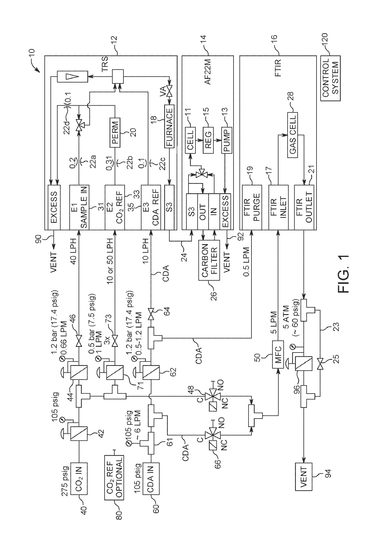
[0076]In this example (referencing FIG. 1), the FTIR is provided with three sample options: (1) off: (2) zero: and (3) sample. The FTIR is controlled by a multi gas software suite such as, for example, the MG2000, reporting to a suitable display software via an AK Interface, for instance. Two solenoid valves (elements 48 and 66 in FIG. 1) and a mass flow controller (MFC 50 in FIG. 1) control sample stream selection and flow rates. When the instrument is in the “off” sample selection, both valves are closed and no gas reaches the FTIR 16. In the zero sample selection, the CDA or nitrogen valve 66 is opened and the MFC 50 is set to a suitable flow rate such as, for example, 5,000 standard cubic centimeter per minute (sccm). After purging the system (e.g., for 10-15 minutes) a new background can be taken in the MG2000 software. This background allows a clean reference single beam for comparison to new sample data.

[0077]The instrument is then placed in sample mode, the nitrogen valve 66...


PUM

PropertyMeasurementUnit
pressuresaaaaaaaaaa
path lengthsaaaaaaaaaa

Abstract

A system and method for determining impurities in a beverage grade gas such as CO2 or N2 relies on a coupling of FTIR analysis and UV fluorescence detection. Conversion of reduced sulphur present in some impurities to SO2 can be conducted using a furnace. In some cases, CO2 % also is determined.

Description

RELATED APPLICATIONS[0001]This application claims the benefit under 35 USC 119(e) of U.S. Provisional Application No. 62 / 466,697, filed on Mar. 3, 2017, and U.S. Provisional Application No. 62 / 468,573, filed on Mar. 8, 2017, both being incorporated herein by reference in their entirety.BACKGROUND OF THE INVENTION[0002]Carbon dioxide (CO2) is a colorless, odorless gas that can be used as an inert material, as pressurized gas, in “dry ice”, liquid or supercritical fluid applications, and many other areas, such as, for instance, oil production and the chemical industry. In the food sector, CO2 is a medium for decaffeination and a feedstock for obtaining carbonated beverages, providing effervescence to water, soft drinks, wine, beer and so forth. Applications such as found in the beverage industry require CO2 of a specified purity. It is important, therefore, to monitor the nature and levels of contaminants in the gas employed.[0003]Some existing systems for analyzing impurities in CO2 ...

Claims


Application Information

Patent Timeline
Patent Type & Authority Patents(United States)
IPC IPC(8): G01N21/3504G01N21/94G01N21/64G01N21/75G01N33/00G01N21/84G01N21/17G01N21/05G01N21/03G01N21/35
CPCG01N21/3504G01N21/643G01N21/75G01N21/94G01N21/031G01N21/0317G01N2021/8411G01N33/0013G01N33/0042G01N2021/174G01N2021/1734G01N2021/354G01N2021/3595G01N21/05
Inventor SPARTZ, MARTIN L.BEHNKE, PETER PAULPHILLIPS, CHARLES MARKKLEMPNER, ADAM R.BONANNO, ANTHONY S.
Owner MLS ACQ INC
Why Eureka
Try Eureka