Flight phase stability indicator system and method

a technology of stability indicator and flight phase, applied in the direction of process and machine control, instruments, navigation instruments, etc., can solve the problems of passengers' deaths and injuries, aircraft's inability to operate in the approach and/or landing operational flight modes, etc., to enhance the pilot's situational awareness

Active Publication Date: 2019-12-24
ROCKWELL COLLINS INC
View PDF11 Cites 3 Cited by
  • Summary
  • Abstract
  • Description
  • Claims
  • Application Information

AI Technical Summary

Benefits of technology

[0004]Embodiments of the inventive concepts disclosed herein are directed to a flight phase stability indicator system and method for generating and presenting stability indicator(s). The inventive concepts disclosed herein could enhance a pilot's situational awareness of the current operational flight phase by monitoring and presenting him or her with instant stability information of the current operational flight phase both textually and graphically with the disclosed stability indicator comprised of a plurality of traversable stability zones and a traversing position indicator. The use of real-time input factors applied to a projected trajectory to provide the pilot(s) with a way to visually monitor the progress of an approach-to-landing on runway by providing real-time advisories including those advisories meeting criteria for the generation of caution and warning stability indications as well as a time to recover from such indications.

Problems solved by technology

Current warnings systems such as the industry standard employed for a Ground Proximity Warnings System (GPWS), Terrain Awareness and Warning System (TAWS), and surface management systems do not address all of the problems; this was evidenced by an accident involving of an Asiana Airlines Boeing 777-200ER at San Francisco International Airport in July 2013.
The accident was attributed to pilot error.
Although they assumed control of the aircraft upon disengagement, they failed to manually engage the throttles, thereby creating an unstable flight mode for an aircraft operating in the approach and / or landing operational flight modes.
As a result of the accident, passengers were killed and injured.

Method used


Image

  • Flight phase stability indicator system and method
  • Flight phase stability indicator system and method
  • Flight phase stability indicator system and method

Examples


Embodiment Construction

[0032]In the following description, several specific details are presented to provide a thorough understanding of embodiments of the invention. One skilled in the relevant art will recognize, however, that the invention can be practiced without one or more of the specific details, or in combination with other components, etc. In other instances, well-known implementations or operations are not shown or described in detail to avoid obscuring aspects of various embodiments of the invention.

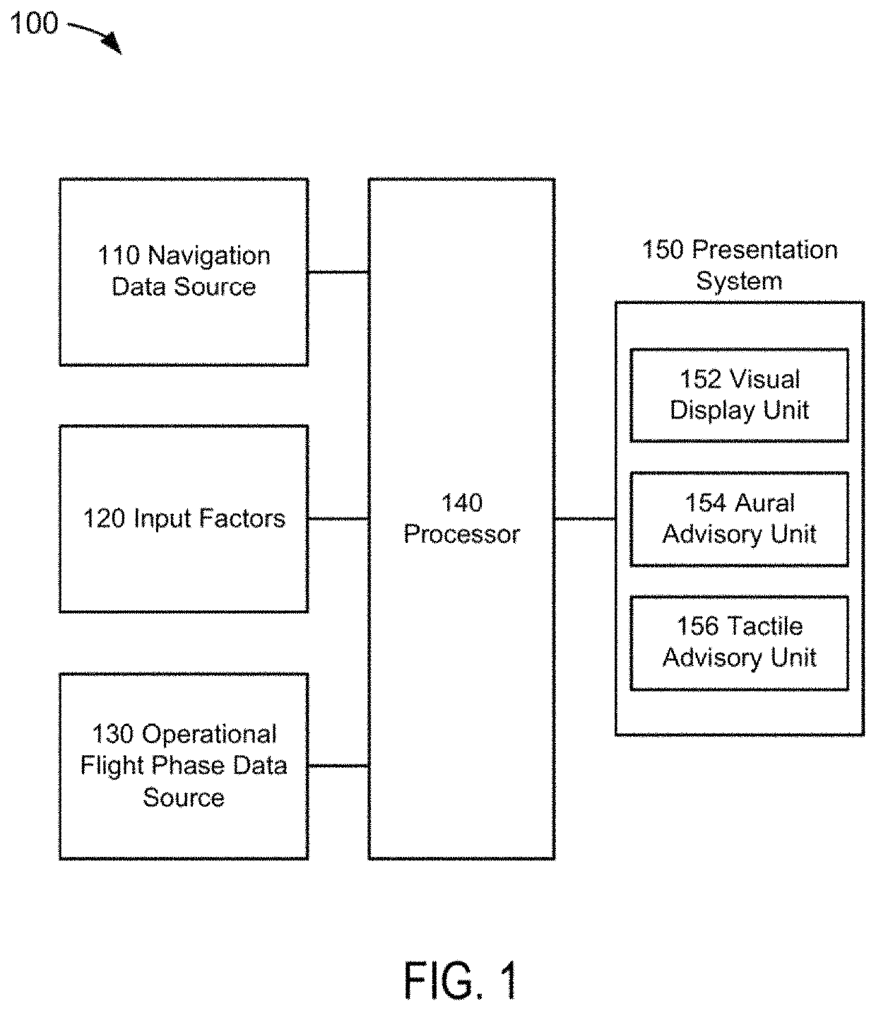
[0033]FIG. 1 depicts a functional block diagram of a geographic position data generation system 100 suitable for implementation of the techniques described herein. The functional blocks of the system may include a navigation data source 110, input factors 120, an operational flight phase data source 130, a processor 140, and a presentation system 150.

[0034]In the embodiment of FIG. 1, the navigation data source 110 could be comprised of a system or systems that may provide navigation data informatio...


PUM


Abstract

A flight phase stability indicator system and method for generating and presenting stability indicator(s) are disclosed. A processor receives flight phase data representative of an identification of a current operational flight phase; receives navigation data comprised of aircraft position, a planned flight trajectory, and runway data if runway data is needed for the current operational flight phase; determines stability data representative of a stability of the current operational flight phase based upon at least the navigation data; generates presentation data responsive to the determination and representative of the flight phase stability indicator and/or presentation(s) of flight phase stability; and presents the indicator represented in the presentation data on or through a presentation unit comprised of a visual display, aural advisory unit, and/or tactile advisory unit.

Description

BACKGROUND OF THE INVENTIONField of the Invention[0001]This invention pertains generally to the field of indicating systems such as, but not limited to, aircraft indicating systems.Description of the Related Art[0002]Runway overruns and underruns have been recognized as major contributors to aviation accidents worldwide. Current warnings systems such as the industry standard employed for a Ground Proximity Warnings System (GPWS), Terrain Awareness and Warning System (TAWS), and surface management systems do not address all of the problems; this was evidenced by an accident involving of an Asiana Airlines Boeing 777-200ER at San Francisco International Airport in July 2013. A shortcoming of these systems is the deliberate “detuning” of the alerting algorithms when operating near airports so that nuisance alerts are inhibited because of deliberate “low and slow” flight operations when an aircraft approaches a runway.[0003]The accident was attributed to pilot error. The pilots were ope...

Claims


Application Information

Patent Timeline
Patent Type & Authority Patents(United States)
IPC IPC(8): G05D1/06B64D17/00
CPCG05D1/0676G05D1/0684B64D17/00B64D45/00G01C23/00
Inventor CARRICO, MATTHEW J.SIPPER, LORI J.NIRAULA, MADHU S.EPPERSON, KIMM M.TALBOTT, CURTIS W.BELL, DOUGLAS A.
Owner ROCKWELL COLLINS INC
Why Eureka
Try Eureka