Cylinder-rotation compressor with improved vane and suction passage locations

a compressor and cylinder technology, applied in the direction of rotary/oscillating piston pump components, machines/engines, liquid fuel engines, etc., can solve the problems of disadvantageous increase in the drive force of the cylinder-rotation, disadvantageous decrease of increase of the energy loss of the compressor, so as to limit the increase in the energy loss of the cylinder-rotation-type compressor and the effect of reducing the pressure of the compression chamber

a compressor and cylinder technology, applied in the direction of rotary/oscillating piston pump components, machines/engines, liquid fuel engines, etc., can solve the problems of disadvantageous increase in the drive force of the cylinder-rotation, disadvantageous decrease of increase of the energy loss of the compressor, so as to limit the increase in the energy loss of the cylinder-rotation-type compressor and the effect of reducing the pressure of the compression chamber

US10533554B2Active Publication Date: 2020-01-14DENSO CORP

Image

  • Cylinder-rotation compressor with improved vane and suction passage locations
  • Cylinder-rotation compressor with improved vane and suction passage locations
  • Cylinder-rotation compressor with improved vane and suction passage locations

Examples


Embodiment Construction

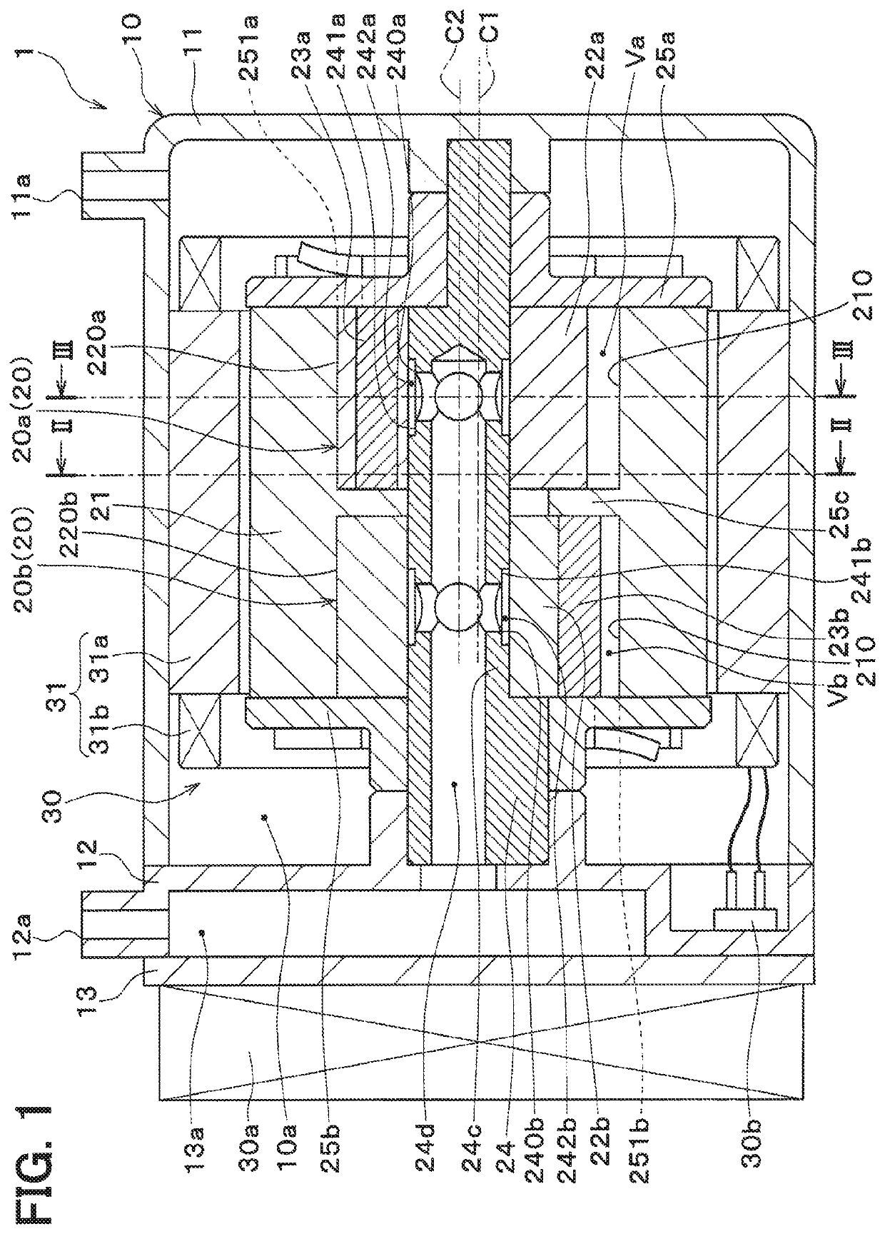
[0033]Hereinafter, an embodiment of the present disclosure will be described with reference to the drawings. A cylinder-rotation-type compressor 1 (hereinafter, simply referred to as a compressor 1) of the present embodiment is applied to a vapor compression type refrigeration cycle system that cools air to be blown into a cabin of a vehicle by an air conditioning apparatus of the vehicle. The compressor 1 has a function of compressing and discharging a refrigerant (serving as compression-subject fluid) at this refrigeration cycle system.

[0034]In this refrigeration cycle system, HFC refrigerant (more specifically, R134a) is used as the refrigerant, and the refrigeration cycle system forms a sub-critical refrigeration cycle, in which a high-pressure-side refrigerant pressure does not exceed a critical pressure of the refrigerant. Furthermore, the refrigerant contains refrigerating machine oil, which is lubricant oil for lubricating slidable parts of the compressor 1, and a portion of...


PUM


Abstract

A primary groove, into which a primary vane is slidably fitted, and a primary rotor-side suction passage, which conducts refrigerant of a shaft-side suction passage of a shaft to a primary compression chamber, are formed at a primary rotor. The primary groove is shaped into a form that extends from an inner peripheral side toward an outer peripheral side and extends toward a rear side with respect to a rotational direction, and the primary rotor-side suction passage is shaped into a form that extends from the inner peripheral side toward the outer peripheral side and extends and tilts toward a front side with respect to the rotational direction. A fluid outlet of the primary rotor-side suction passage opens at a location that is immediately after the primary groove on the rear side of the primary groove with respect to the rotational direction.

Description

CROSS REFERENCE TO RELATED APPLICATIONS[0001]This application is the U.S. national phase of International Application No. PCT / JP2016 / 002186 filed on Apr. 26, 2016 and is based on and incorporates herein by reference Japanese Patent Application No. 2015-106284 filed on May 26, 2015.TECHNICAL FIELD[0002]The present disclosure relates to a cylinder-rotation-type compressor that rotates a cylinder, which forms a compression chamber in an inside of the cylinder.BACKGROUND ART[0003]Previously, the patent literature 1 discloses a cylinder-rotation-type compressor that rotates a cylinder, which forms a compression chamber in an inside of the cylinder, while an outer-peripheral-side end portion of a vane abuts against an inner peripheral surface of the cylinder.[0004]The cylinder-rotation-type compressor of the patent literature 1 includes the cylinder, a rotor, a shaft and the vane. The cylinder is shaped into a cylindrical tubular form. The rotor is shaped into a cylindrical tubular form a...

Claims


Application Information

Patent Timeline
14 Jan 2020
Publication
US10533554B2
IPC
F04C18/344; F04C23/00; F04C29/12
CPC
F04C29/12; F04C18/3441; F04C2240/603; F04C23/001; F04C2240/20
Inventors
OHNO, YUICHI; OGAWA, HIROSHI