Supercharge Your Innovation With Domain-Expert AI Agents!

Signal processing apparatus, control method, image pickup element, and electronic device

a technology of image pickup and signal processing, applied in the direction of color television details, television system details, television systems, etc., can solve the problems of increasing cost and the risk of another noise, and achieve the effect of suppressing rts nois

Active Publication Date: 2020-01-14
SONY CORP
View PDF21 Cites 0 Cited by
  • Summary
  • Abstract
  • Description
  • Claims
  • Application Information

AI Technical Summary

Benefits of technology

[0030]According to the present technology, it is possible to process a signal. Also, according to the present technology, it is possible to suppress RTS noise.

Problems solved by technology

However, there is a risk of occurrence of another noise such as aggravated noise resulting from a kickback or simultaneous inversion of comparator output.
However, there is a need to modify a process, and is a risk of increasing cost.

Method used


Image

  • Signal processing apparatus, control method, image pickup element, and electronic device
  • Signal processing apparatus, control method, image pickup element, and electronic device
  • Signal processing apparatus, control method, image pickup element, and electronic device

Examples


first embodiment

1. First Embodiment

[0055]

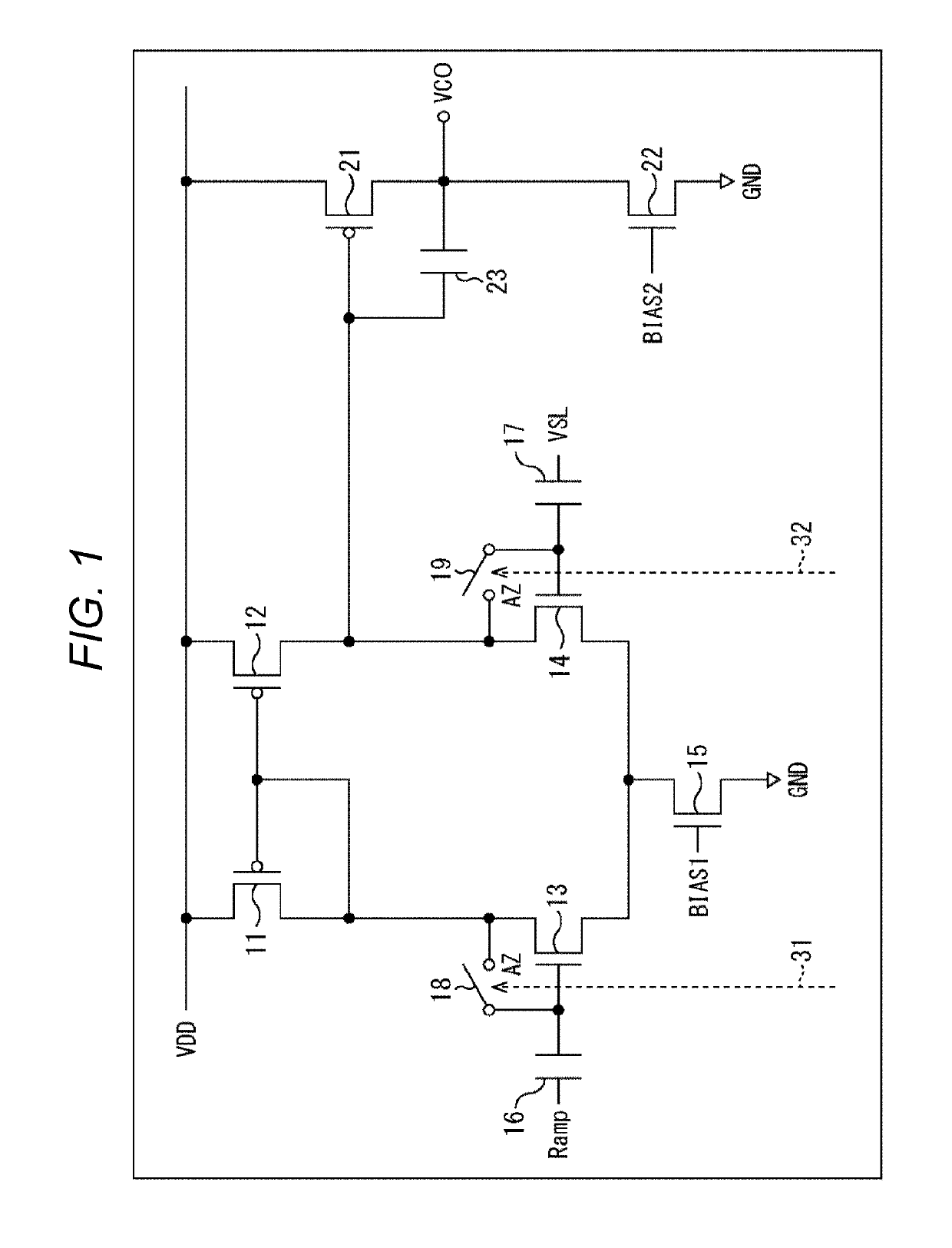
[0056]For analog circuits used for image sensors and the like, in particular, A / D converters, there have been conventionally made various attempts to reduce noise. For example, a comparator (also referred to as a comparison unit) is used for a common A / D converter.

[0057]FIG. 1 illustrates a main configuration example of a common comparison unit. As illustrated in FIG. 1, the common comparison unit includes a differential stage and an amplifier stage. The comparison unit includes, as the differential stage, transistors 11 to 15, capacitors 16 and 17 as an input capacitance, and switches 18 and 19 which perform an auto-zero process by short-circuiting an input side and an output side of the comparison unit. The switches 18 and 19 are supplied with a control signal from a control unit (not illustrated) through control lines 31 and 32, respectively, and are driven (perform an ON / OFF operation) on the basis of the control signal. Also, the comparison unit include...

second embodiment

2. Second Embodiment

[0164]

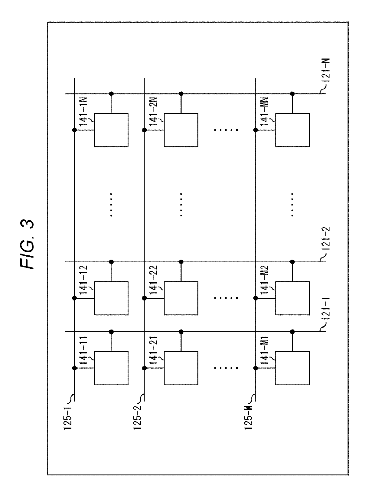
[0165]For example, the present technology can also be applied to a pixel array 101, a unit pixel 141. A main configuration example of the unit pixel 141 in that case is illustrated in FIG. 15.

[0166]In the case of the example illustrated in FIG. 15, the unit pixel 141 includes a switch 361 in addition to the configuration in the example in FIG. 4. The switch 361 is provided between a floating diffusion (FD) and a ground potential (GND), is driven in accordance with a control signal STRTS supplied from a control unit 111 through a control line 362 (in other words, in accordance with the control of the control unit 111), and is capable of short-circuiting the floating diffusion (FD) to the ground potential. That is to say, the switch 361 is capable of short-circuiting a gate of an amplifying transistor 154 to a potential which reduces a gate-to-source voltage of the amplifying transistor 154.

[0167]A control process of that case is basically similar to that of ...

third embodiment

3. Third Embodiment

[0168]

[0169]It should be noted that an image pickup element to which the present technology is applied can be realized, for example, as a package (chip) in which a semiconductor substrate is sealed or a module in which the package (chip) is placed on a circuit substrate. For example, in a case where it is realized as a package (chip), the image pickup element may be configured by a single semiconductor substrate in the package (chip), or may be configured by multiple semiconductor substrates overlapping each other.

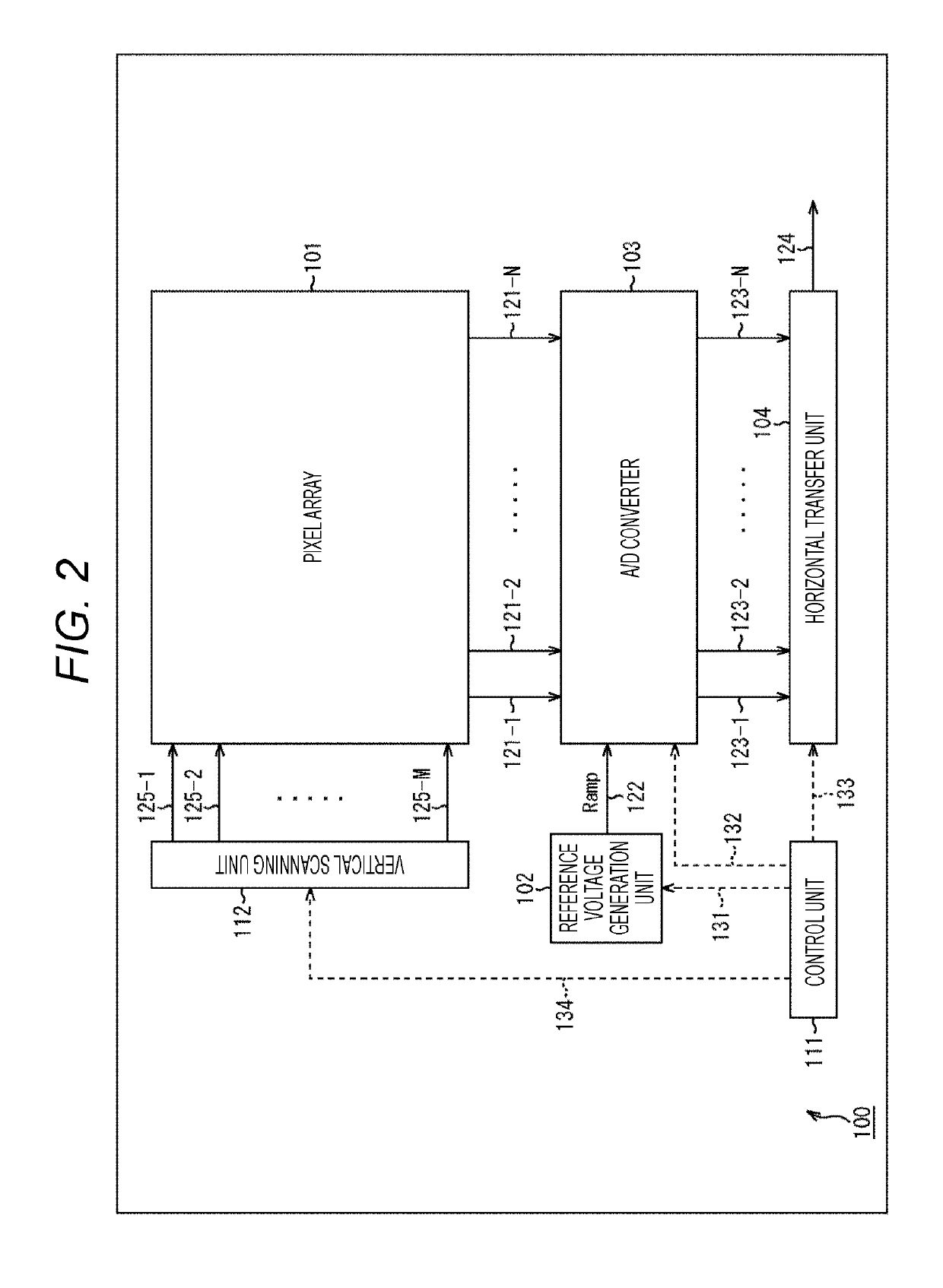
[0170]FIG. 16 is a diagram illustrating an example of a physical configuration of an image sensor 100, which is an image pickup element to which the present technology is applied.

[0171]In the case of an example illustrated in A of FIG. 16, all circuit configurations of the image sensor 100 described with reference to FIG. 2 and the like are formed on a single semiconductor substrate. In the case of the example in A of FIG. 16, output units 404-1 to 404-4...


PUM


Abstract

The present technology relates to a signal processing apparatus, a control method, an image pickup element, and an electronic device which make it possible to suppress RTS noise. The signal processing apparatus of the present technology may include an amplifying transistor and a short-circuit unit. The amplifying transistor amplifies a signal input to a gate, and the short-circuit unit is capable of short-circuiting the gate of the amplifying transistor to a potential which reduces a gate-to-source voltage of the amplifying transistor. For example, it is determined whether the amplifying transistor is in a period of a non-operating state, and when the amplifying transistor is determined to be in the period of a non-operating state, the gate of the amplifying transistor may be short-circuited. The present technology can be applied, for example, to an image pickup element and an electronic device.

Description

CROSS REFERENCE TO RELATED APPLICATIONS[0001]This application is a national stage application under 35 U.S.C. 371 and claims the benefit of PCT Application No. PCT / JP2015 / 072949 having an international filing date of 14 Aug. 2015, which designated the United States, which PCT application claimed the benefit of Japanese Patent Application No. 2014-170470 filed 25 Aug. 2014, the disclosures of which are incorporated herein by reference in their entirety.TECHNICAL FIELD[0002]The present technology relates to a signal processing apparatus, a control method, an image pickup element, and an electronic device, and particularly relates to a signal processing apparatus, a control method, an image pickup element, and an electronic device, which make it possible to suppress RTS noise.BACKGROUND ART[0003]Conventionally, noise countermeasures have been taken against random telegraph signal (RTS) noise occurring in transistors, in image sensors and the like. For example, a method is considered in...

Claims


Application Information

Patent Timeline
Patent Type & Authority Patents(United States)
IPC IPC(8): H04N5/365H04N5/374H04N5/378
CPCH04N5/365H04N5/374H04N5/378H04N5/3651H04N25/67H04N25/671H04N25/76H04N25/75
Inventor HANZAWA, KATSUHIKO
Owner SONY CORP
Features
  • R&D
  • Intellectual Property
  • Life Sciences
  • Materials
  • Tech Scout
  • Unparalleled Data Quality
  • Higher Quality Content
  • 60% Fewer Hallucinations
Learn More