Intershaft seal with dual opposing carbon seal rings

a technology of intershaft seals and carbon seals, which is applied in the direction of engines, machines/engines, gas turbine plants, etc., can solve the problems of little axial space in the available space for packaging and positioning radial intershaft seals

Active Publication Date: 2020-02-18
GENERAL ELECTRIC CO
View PDF20 Cites 1 Cited by
  • Summary
  • Abstract
  • Description
  • Claims
  • Application Information

AI Technical Summary

Problems solved by technology

Sometimes, there is very little axial room in the available space to package and locate radial intershaft seals such as labyrinth seals.

Method used


Image

  • Intershaft seal with dual opposing carbon seal rings
  • Intershaft seal with dual opposing carbon seal rings
  • Intershaft seal with dual opposing carbon seal rings

Examples


Embodiment Construction

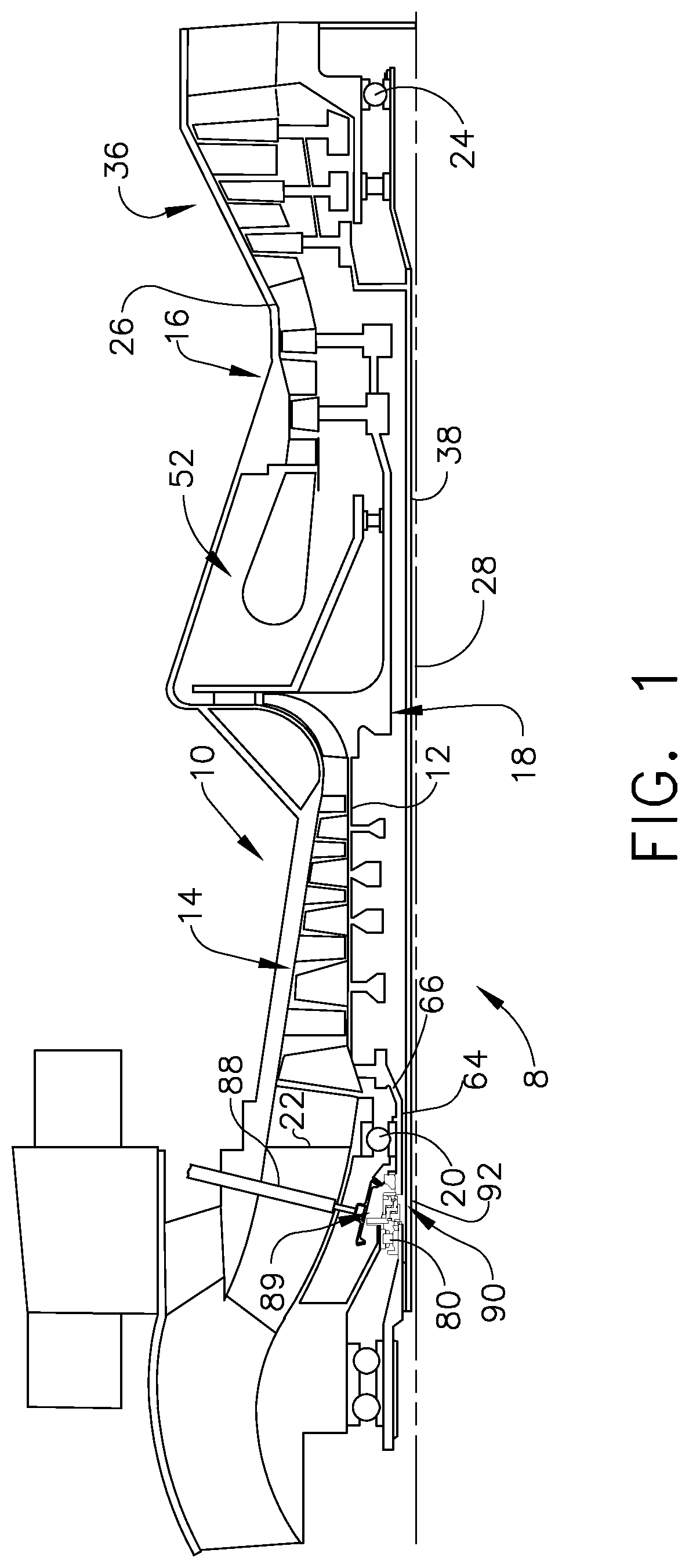
[0019]Illustrated in FIG. 1, gas turbine engine assembly 8 with a high pressure gas generator 10 having a single stage centrifugal compressor 18 as a final compressor stage. The high pressure gas generator 10 has a high pressure rotor 12 including, in downstream flow relationship, a high pressure compressor 14, a combustor 52, and a high pressure turbine 16. The rotor 12 is rotatably supported about an engine centerline 28 by a first or forward bearing 20 in a front frame 22 and a rear bearing 24 disposed downstream of the high pressure turbine 16 in a turbine frame 26.

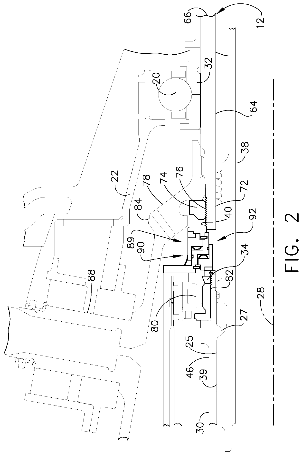
[0020]Referring further to FIG. 2, a stub shaft 64 is located at a front end 66 of the high pressure rotor 12 to which it is connected. A high pressure lock-nut 74 is threaded on forward threads 76 on a forward end 72 of the stub shaft 64. The high pressure lock-nut 74 is used to tighten, secure, and clamp together and place in compression a horizontal bevel gear 78 and a ball bearing inner race 32 of the forward bear...


PUM


Abstract

An intershaft seal assembly including first and second or forward and aft carbon face seal rings supported on an annular housing and having first and second seal faces facing in opposite directions. Forward and aft springs operably disposed between housing and carbon face seal rings for biasing or urging carbon face seal rings in opposite directions. Annular forward and aft carriers mounted on and supported by annular housing and supporting carbon face seal rings. Forward and aft springs operably disposed between housing and the forward and aft carriers respectively. The springs may be wave springs. Inner and outer secondary seals may include inner and outer O rings disposed in annular inner and outer grooves in annular inner and outer surfaces in housing respectively and in sealing engagement with the forward and aft carriers. Carriers may be integral with carbon face seal rings in monolithic combined seal and carrier elements.

Description

TECHNICAL FIELD[0001]The present invention relates generally to intershaft air and oil seals and, more specifically, for such seals carbon sealing elements.BACKGROUND INFORMATION[0002]Air or oil sealing is often required between two opposing shafts such as is found in gas turbine engines. Sometimes, there is very little axial room in the available space to package and locate radial intershaft seals such as labyrinth seals.[0003]Thus, there continues to be a need for air and oil intershaft seals which provide lighter weight seal assemblies that occupy smaller volumes with less leakage than labyrinth seals and other conventional seals. It is desirable to provide intershaft sealing in a tight design space that would otherwise require a less desirable seal such as a labyrinth seal between concentric shafts.BRIEF DESCRIPTION OF THE INVENTION[0004]An intershaft seal assembly includes first and second or forward and aft carbon face seal rings supported on an annular housing, first and seco...

Claims


Application Information

Patent Timeline
Patent Type & Authority Patents(United States)
IPC IPC(8): F01D11/00F01D5/02
CPCF01D11/003F01D5/026F05D2240/55F05D2260/30F02C7/28
Inventor WOTZAK, MARK GREGORY
Owner GENERAL ELECTRIC CO
Why Eureka
Try Eureka