Speed change device with coaxial connecting rod rolling disc

A speed change device and rolling disc technology, which is applied to the transmission device, transmission device parts, friction transmission device, etc., can solve the problems affecting the actuation of the speed change device and the operation of the shaft

Pending Publication Date: 2018-03-06
陈鹏宇
View PDF3 Cites 2 Cited by
  • Summary
  • Abstract
  • Description
  • Claims
  • Application Information

AI Technical Summary

Problems solved by technology

[0005] Furthermore, in addition to a clutch shaft in the transmission disc, the known speed change device also has a secondary shaft and a main shaft, wherein the clutch shaft is connected with the driving shaft of a motor, and the secondary shaft and the main shaft are respectively pierced with a pair The opposite chainring, that is, a front chainring and a rear chainring, the gear ratio of the front chainring and the rear chainring is 1:2, so that during operation, the shaft torque of t

Method used


Image

  • Speed change device with coaxial connecting rod rolling disc
  • Speed change device with coaxial connecting rod rolling disc
  • Speed change device with coaxial connecting rod rolling disc

Examples


Embodiment Construction

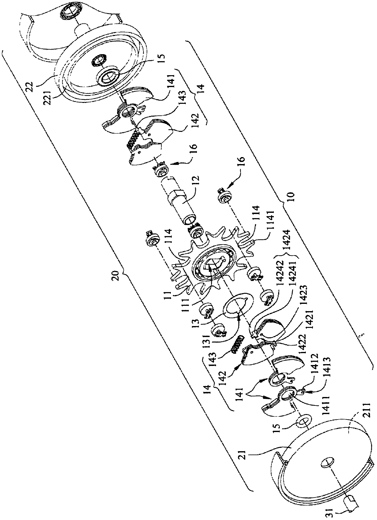
[0052] In order to facilitate your examiner to have a further understanding and understanding of the technical means and operation process of the present invention, here is an example with accompanying drawings, and the detailed description is as follows:

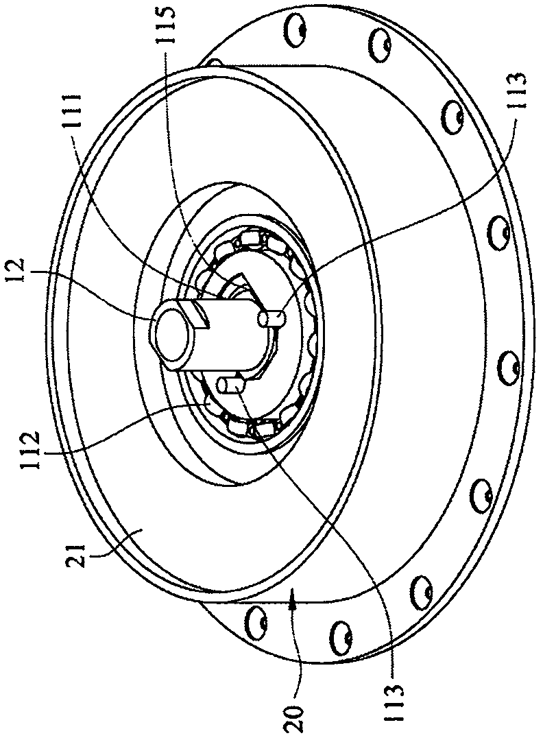
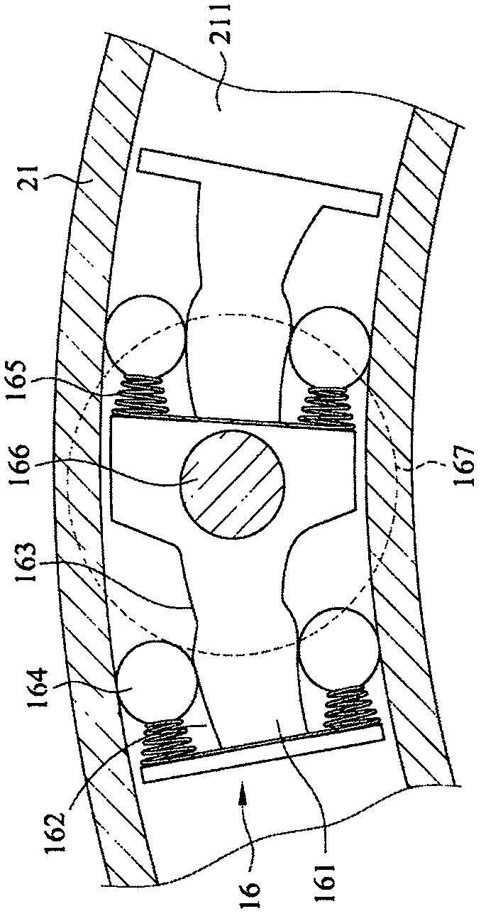
[0053] see figure 1 As shown, the present invention provides a speed change device for coaxial connecting rod rollers, which includes a body 10 and a transmission housing 20, the body 10 is arranged in the transmission housing 20, wherein one side of the transmission housing 20 has A hollow annular first clutch disc 21, the edge ring of the first clutch disc 21 is provided with a recessed sliding groove 211, the transmission case 20 has a second clutch disc 22 on the opposite side of the first clutch 21, and A sliding groove 221 is arranged around the edge of the second clutch groove 22 and opposite to the first clutch groove 21. The center of the second clutch groove 22 has a through shaft hole 222, and the shaft hole 222...


PUM


Abstract

The invention relates to a speed change device with a coaxial connecting rod rolling disc. The speed change device comprises a speed changer shell containing a body. The body comprises the coaxial connecting rod rolling disc, a force-input shaft, a centrifugal piece, a plurality of counterweight assemblies, a plurality of O rings and a plurality of sliding block assemblies. When the speed change device conducts actuation, the force-input shaft serves as a force applying point of the lever principle, the equal sliding block assemblies serve as weight points, and the arm of force is equal to thedistance between the force-input shaft and each equal sliding block assembly; the equal sliding block assemblies are arranged at the tail end of the connecting rod rolling disc, therefore, compared with the prior art, the arm of force is increased, the bearing force of the weight points is improved, the turning force of the speed change device is increased under the same motor force, and accordingly the motor force is saved; and in addition, U-shaped grooves for containing the equal sliding block assemblies are formed in the tail end of the connecting rod rolling disc, so that machining is easy during manufacturing, and the cost can be reduced.

Description

technical field [0001] The invention relates to a speed change device, in particular to a speed change device with a coaxial connecting rod roller with an eccentric wheel of the connecting rod roller. Background technique [0002] The speed change device is often installed on a motor vehicle or an electric bicycle. The slider body in the speed change device is driven by a motor to rotate the speed change device, which further drives the wheels to rotate, so that the car and motorcycle can move forward. [0003] see Figure 8 As shown, a conventional speed change device 60 is through a plurality of hollow holes 62 engraved on a speed change plate 61, and a plurality of slider bodies 63 are assembled on the speed change plate 61, and by rotating the speed change plate 61, these The slider body 63 rotates; in action, an input shaft 64 of the speed change device 60 is used as the force point, and the slider bodies 63 are gravity points. At this time, the length L of a moment arm...

Claims


Application Information

Patent Timeline
IPC IPC(8): F16H57/023F16H15/40
CPCF16H15/40F16H57/023
Inventor 陈鹏宇
Owner 陈鹏宇
Why Eureka
Try Eureka