Swimming pool wall having a drainage groove

a technology of pool wall and drainage groove, which is applied in the direction of public buildings, gymnasiums, buildings types, etc., can solve the problems of complex transition between the pool wall and the drain wall, difficulty in welding stainless steel, and high cost, and achieves easy and simple mounting, increased impermeability of the swimming pool, and cost saving

Active Publication Date: 2020-03-03
BERNDORF BADERBAU SRO
View PDF1 Cites 0 Cited by
  • Summary
  • Abstract
  • Description
  • Claims
  • Application Information

AI Technical Summary

Benefits of technology

[0013]This technical solution is simple, requires no joining of the stainless steel parts and enables an easy and simple mounting of the drainage groove cover grids. All these technical measures lead to cost savings, increase the swimming pool impermeability and accelerate their construction.
[0015]Another beneficial technical effect of this technical solution consists in allowing a better cover of the swimming pool water surface by a cover shutter, as it allows to cover the whole water surface of the swimming pool. This reduces the energy losses caused by evaporation.

Problems solved by technology

For these reasons, stainless steel swimming pools with a high standard of hygiene are produced for these purposes, but their production is technically difficult and therefore costly.
The connection is preferably realized by welding, but the welding of stainless steel is difficult and costly.
Also the transition between the pool wall and the drain wall is complicated from a technical point of view.
Similarly, the mounting of drainage grid covers is technically demanding.
All these drawbacks lead to increased swimming pool costs and the occurrence of deformations at the welding site, as well as to the permanent risk of leakage of the weld joint.

Method used


Image

  • Swimming pool wall having a drainage groove
  • Swimming pool wall having a drainage groove

Examples


exemplary embodiment number 1

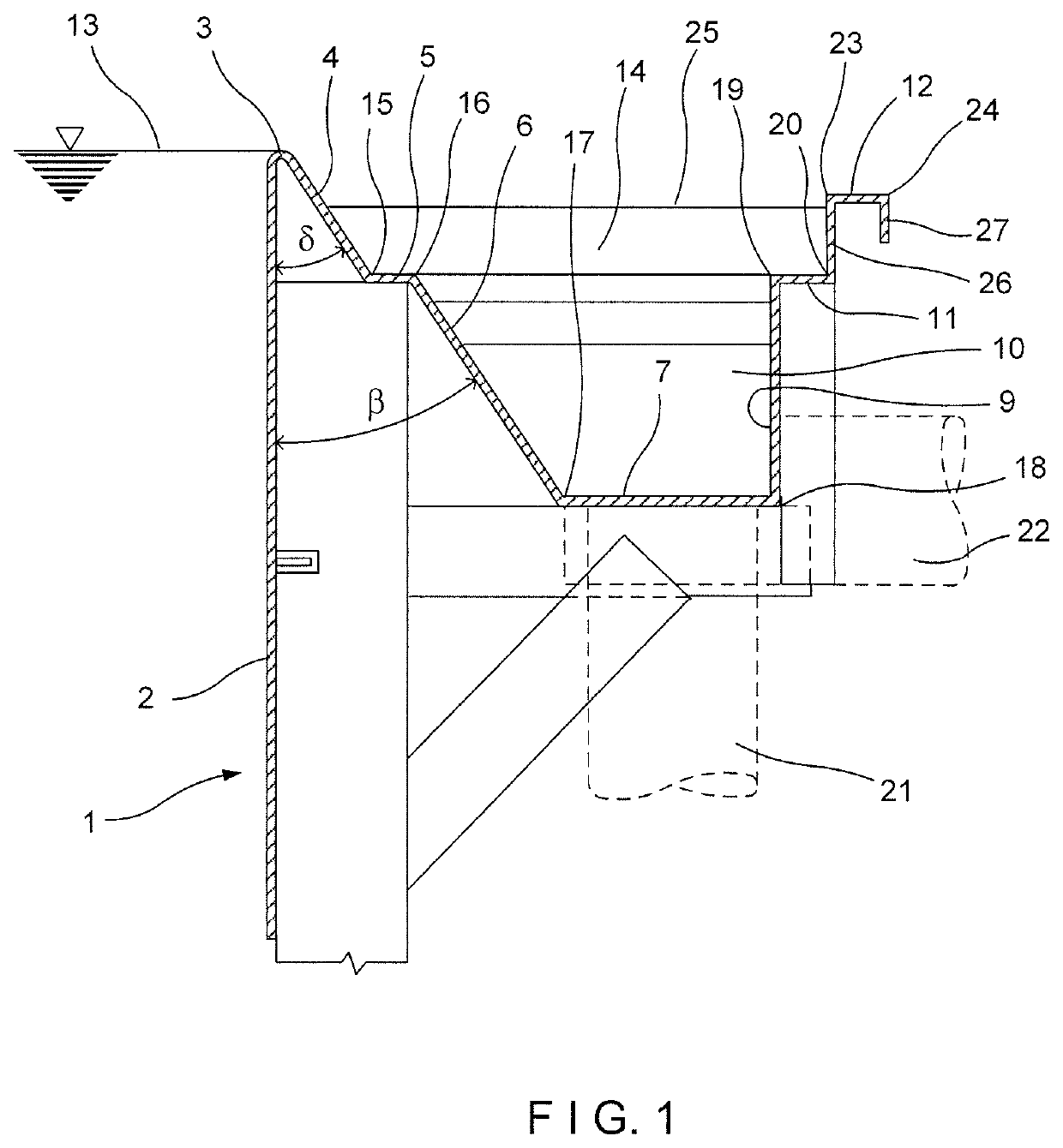
[0019]FIG. 1 shows a profile of a swimming pool wall with an overflow edge and a groove which in the direction 1 shows a sectional view of the profiled swimming pool wall made of a one piece of a metal plate shaped by mechanical shaping, the groove 10 being provided with two L profiles which form the support for the attachment of the grid 14.

[0020]The outer jacket of the pool is engineered as a mechanically shaped wall made of a single piece of a stainless steel plate.

[0021]The vertical side wall 2 of the swimming pool forms by means of a bend at an acute angle δ with the slope wall 4 an overflow edge 3 for the swimming pool water level 13.

[0022]The slope wall 4 can be in the vertical plane higher than the upper portion 35 of the grid 14 by at least 15 mm, as measured vertically, to form a safety grip according to the safety standard.

[0023]The slope wall 4 extends in the form of a beveled L profile with a first bend 15 at an obtuse angle 90°+δ in the horizontal direction, where it f...

exemplary embodiment number 2

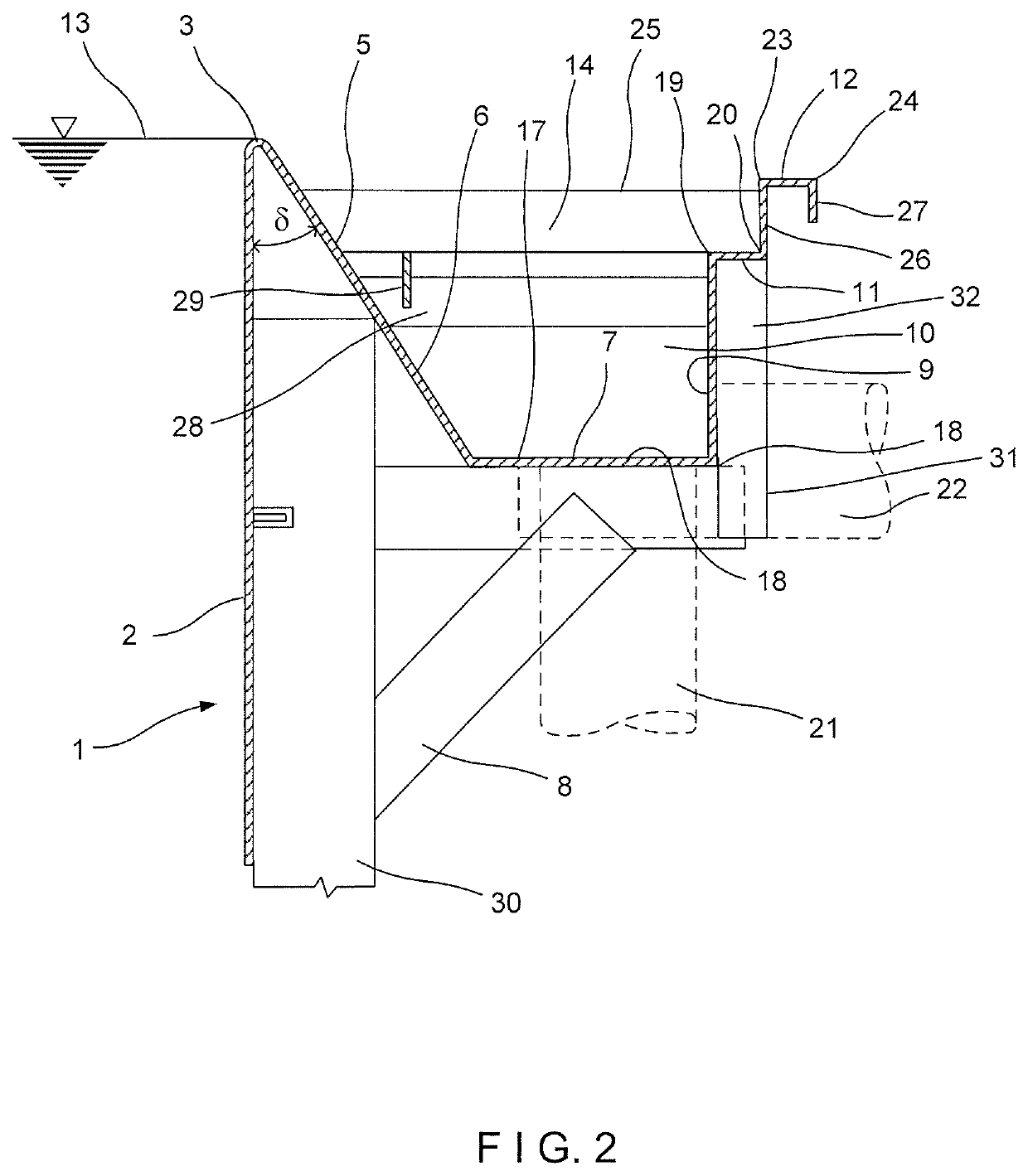
[0031]FIG. 2 represents a profile of the swimming pool wall with an overflow edge and a groove and shows in the direction 1 in a sectional view the profiled pool wall made of a one piece of a metal plate shaped by mechanical shaping, the groove 10 being provided with only one L profile which forms one support for attaching the grid 14, and the second grid support being represented by a horizontal rib 28 with a continuously welded horizontal counter element 29.

[0032]The outer jacket of the pool is engineered as a mechanically shaped wall made of a single piece of a stainless steel plate. The vertical side wall 2 of the swimming pool forms by means of a bend at an acute angle δ with the slope wall 4 an overflow edge 3 for the swimming pool water level 13. The slope wall 4 can be in the vertical plane higher than the upper portion 35 of the grid 14 by at least 15 mm, as measured vertically, to form a safety grip according to the safety standard.

[0033]The slope wall 4 continues at an an...


PUM


Abstract

A swimming pool wall having a drainage groove. The side wall (2) of the swimming pool and the drainage groove (10) are formed from a single piece of material. The slope wall (4) of the drainage groove (10), which is linked to the side wall (2) of the swimming pool, directly adjoins the swimming pool overflow edge (3).

Description

TECHNICAL FIELD[0001]This invention relates to a swimming pool wall having a drainage groove which is made of a single piece of material, and which is intended especially for relaxation and children's swimming pools where higher water temperature and high hygienic standard are required, especially for bathing, relaxation and relaxation pools and swimming pools for bathing children or for swimming pools for sanitary use.BACKGROUND ART[0002]Currently, requirements for a higher hygiene standard for all types of swimming pools are increasing, especially in connection with the increasing sensitivity of users to allergies, chemical water treatment and the use of skin care products by users. For these reasons, stainless steel swimming pools with a high standard of hygiene are produced for these purposes, but their production is technically difficult and therefore costly.[0003]An example may be a technical solution according to European Patent EP 899 397. In this case, the pool wall is made...

Claims


Application Information

Patent Timeline
Patent Type & Authority Patents(United States)
IPC IPC(8): E04H4/12
CPCE04H4/12E04H4/1227E04H4/0031
Inventor CIESLAR, RUDOLF
Owner BERNDORF BADERBAU SRO
Why Eureka
Try Eureka