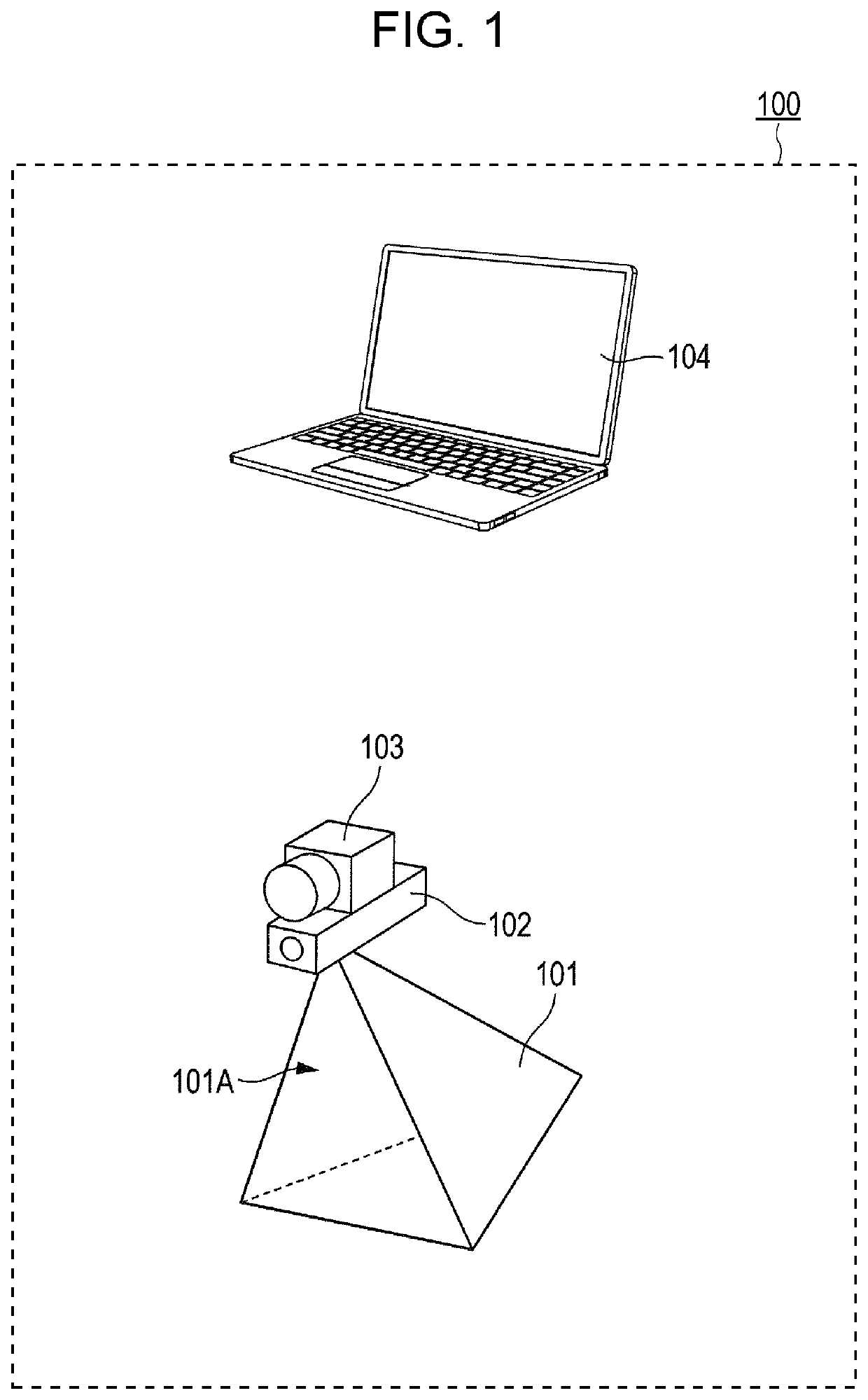
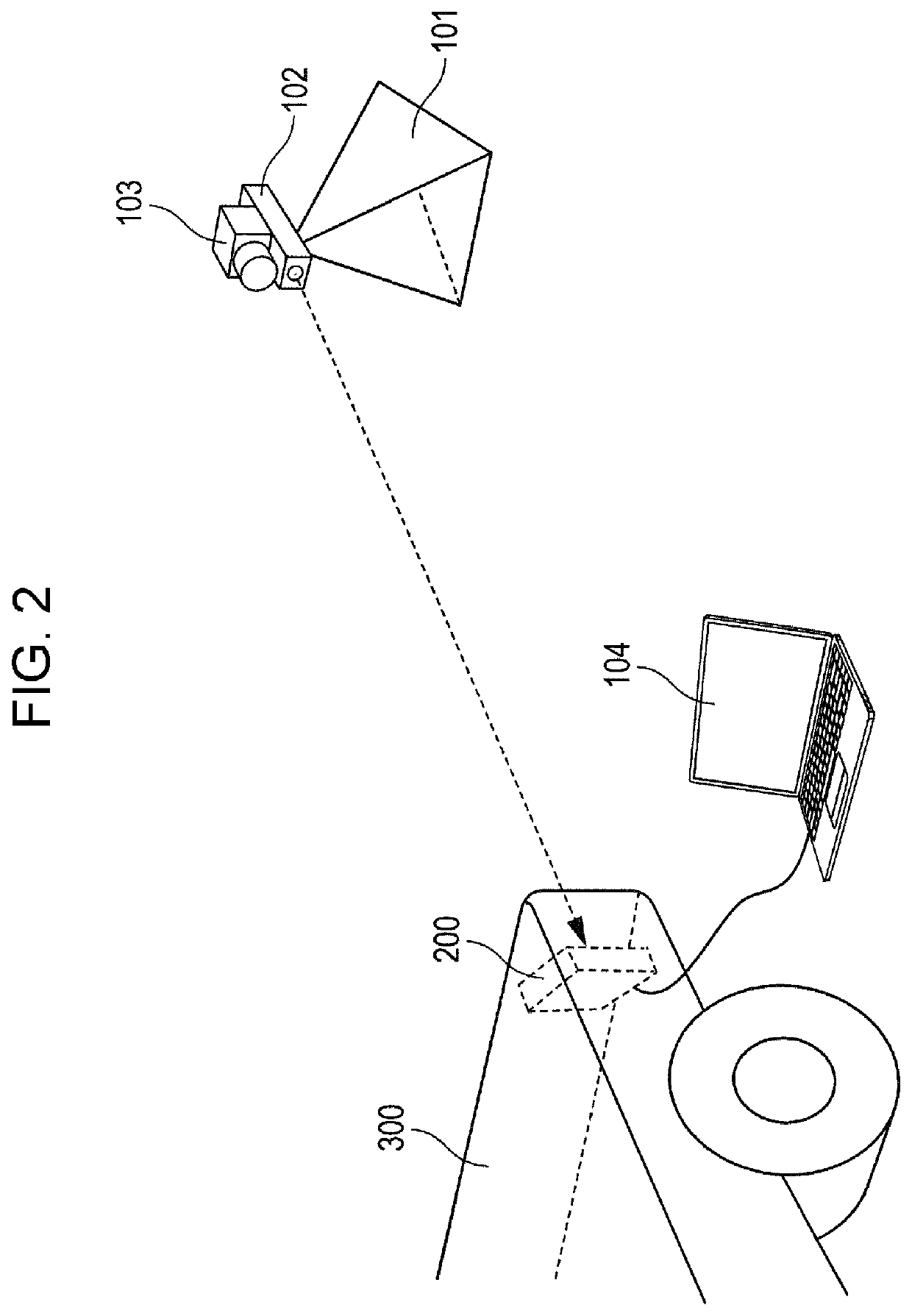
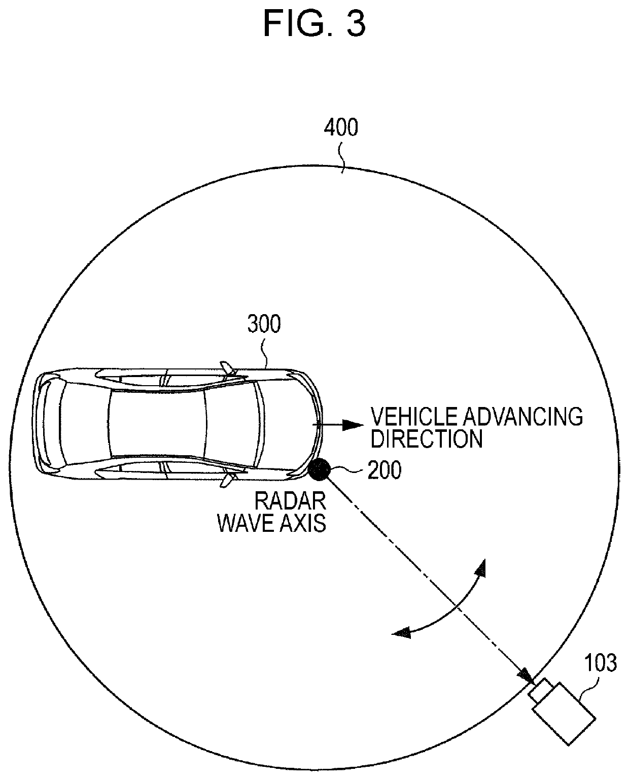
Radar axis displacement amount calculation device and radar axis displacement calculation method

a technology of axis displacement and calculation device, which is applied in the direction of measurement device, using reradiation, instruments, etc., can solve the problems of not being able to apply to the axis adjustment of the installed radar, and achieve the effect of accurately calculating and high installation flexibility of the radar

Active Publication Date: 2020-03-03
PANASONIC CORP
View PDF18 Cites 6 Cited by
  • Summary
  • Abstract
  • Description
  • Claims
  • Application Information

AI Technical Summary

Benefits of technology

[0006]One non-limiting and exemplary embodiment provides a radar axis displacement amount calculation device that achieves high installation flexibility of a radar and is capable of accurately calculating a displacement amount between a radar axis that is a direction of the radar transmission wave transmitted by the radar and a reference direction that is a direction serving as a reference of the radar transmission wave transmitted by the radar, and a method of calculating a radar axis displacement amount.
[0008]The radar axis displacement amount calculation device according to one aspect of the present disclosure provides a high installation flexibility of the radar and is capable of calculating a displacement amount between the radar axis and reference direction with high accuracy.

Problems solved by technology

However, the technique disclosed in Japanese Patent No. 3511605 aligns the radar axis with a direction parallel with the travel direction of the vehicle, and therefore is not applicable to axis adjustment of a radar installed with the radar axis thereof aligned with a direction not parallel with the travel direction of the vehicle.
Also, the technique disclosed in Japanese Patent No. 3511605 is applied to a radar that measures distance and direction to the target in the horizontal direction, and therefore is not applicable to a radar (for example, a radar installed on a construction machine) that is required to achieve high accuracy in estimation of distance and direction in the vertical direction as well.

Method used


Image

  • Radar axis displacement amount calculation device and radar axis displacement calculation method
  • Radar axis displacement amount calculation device and radar axis displacement calculation method
  • Radar axis displacement amount calculation device and radar axis displacement calculation method

Examples


first application example

[0068]Hereinafter, an application example of the radar axis displacement amount calculation device 100 according to the above embodiment of the present disclosure is described. FIG. 9 illustrates a first application example of the radar axis displacement amount calculation device 100.

[0069]As illustrated in FIG. 9, in the first application example of the radar axis displacement amount calculation device 100, a vehicle 300_1 is disposed on a belt conveyor 500, and the radar axis displacement amount calculation device 100 is placed outside the belt conveyor 500. The belt conveyor 500 moves, for example, in the upward direction in FIG. 9, and along with this motion, the vehicle 300_1 also moves in the upward direction in FIG. 9. Then, the radar axis displacement amount calculation device 100 calculates the displacement amount of the radar axis of the radar 200_1 mounted on the vehicle 300_1. The displacement amount calculated by the radar axis displacement amount calculation device 100...

second application example

[0086]FIG. 11 illustrates a second application example of the radar axis displacement amount calculation device 100. In the second application example, multiple radar axis displacement amount calculation devices are installed unlike the first application example where one radar axis displacement amount calculation device is installed. In the second application example, as illustrated in FIG. 11, radar axis displacement amount calculation devices 100_1 and 100_2 are installed, and radars 200_1 and 200_2 simultaneously detect radar axis displacement amount calculation devices 100_1 and 100_2 located at positions (directions) different from each other. Thus, radars 200_1 and 200_2 can acquire second position information of radar axis displacement amount calculation devices 100_1 and 100_2 to be detected, and thereby a direction table used for deriving the direction in radars 200_1 and 200_2 can be corrected accurately.

third application example

[0087]FIG. 12 illustrates a third application example of the radar axis displacement amount calculation device 100. In the third application example, the radar axis displacement amount calculation device 100 of the first application example can move on a rail 600 laid in parallel with the belt conveyor 500.

[0088]In the first and second application examples described above, when the belt conveyor 500 continues on operating, too fast operation speed v of the belt conveyor 500 reduces a time for calculation of the displacement amount by the radar axis displacement amount calculation device 100. In such a case, there may occur a situation where the radar axis displacement amount calculation device 100 is not able to calculate the displacement amount in an appropriate manner. In the third application example, to prevent occurrence of such situation, the radar axis displacement amount calculation device 100 moves on the rail 600 at the same speed as the operation speed v of the belt conve...


PUM


Abstract

A processor generates first position information on a relative position between a camera and a radar, acquires, from the radar, second position information on a relative position between the radar and a reflector, the second position information being generated by using an arrival direction of the radar transmission wave, and calculates a displacement amount by comparing the first position information and the second position information with each other.

Description

BACKGROUND1. Technical Field[0001]The present disclosure relates to a radar axis displacement amount calculation device capable of calculating a displacement amount between a radar axis that is a direction of a radar transmission wave transmitted by a radar provided on a vehicle, a construction machine or the like, and a reference direction that is a direction serving as a reference of the radar transmission wave transmitted by the radar, and a method of calculating a radar axis displacement amount.2. Description of the Related Art[0002]A technique of acquiring information such as relative position, relative speed and direction with respect to a target object using a radar as a sensor is used widely. For example, there is a technique of measuring a moving speed and direction of an object (such as an obstacle) around a vehicle, and a distance between the object and a vehicle by using a radar mounted on the vehicle. Also, for example, there is an attempt to obtain detailed three dimen...

Claims


Application Information

Patent Timeline
Patent Type & Authority Patents(United States)
IPC IPC(8): G01S7/40G01S13/931G01S13/93
CPCG01S13/931G01S7/4026G01S2013/93271G01S2007/4086G01S2007/4034G01S2007/403G01S2013/93275G01S7/40G01S7/4034G01S7/403G01S7/4086
Inventor YOMO, HIDEKUNIMATSUOKA, AKIHIKO
Owner PANASONIC CORP
Why Eureka
Try Eureka