Antenna Assembly

Inactive Publication Date: 2014-07-10
HARADA IND OF AMERICA
View PDF5 Cites 5 Cited by
  • Summary
  • Abstract
  • Description
  • Claims
  • Application Information

AI Technical Summary

Benefits of technology

[0012]Yet another aspect of the present invention provides for a method of coupling an antenna to a vehicle. The method includes the step of preparing a vehicle component having a housing made of a non-metallic material and having a surface made of a metallic material. Additionally, the method includes the step of placing a high-gain film-type antenna element having an input for receiving a wireless signal, an output, and a ground portion on the non-metallic housing of the vehicle component. The method further includes the steps of placing a low noise amplifier in the vehicle component. A coaxial cable is coupled to the output of the film-type antenna element. A ground wire is coupled to the ground portion of the film-type antenna element and to the metallic surface of the vehicle to provide an adequate ground to the assembly. The method provides for an improved performance of the assembly based on the configuration of the assembly.
[0013]The aspects disclosed herein provide various advantages. For example, the use of a film-type antenna element enables increased flexibility of installation in the vehicle without altering the vehicle's styling or external appearance. The film-type antenna element also allows for improved passive performance

Problems solved by technology

However, such a rod-type antenna may inhibit the driver's visibility and/or take away from the visual appeal or look of the vehicle, thus making the vehicle less desirable in the market.
However, as with rod-type antennas, such windshield antennas have their limitations.
Additionally, such windshield mounted antennas are typically low-gain antennas and require further signal amplific

Method used


Image

  • Antenna Assembly
  • Antenna Assembly
  • Antenna Assembly

Examples


Example

[0022]Detailed examples of the present disclosure are disclosed herein; however, it is to be understood that the disclosed examples are merely exemplary and may be embodied in various and alternative forms. It is not intended that these examples illustrate and describe all possible forms of the invention. Rather, the words used in the specification are words of description rather than limitation, and it is understood that various changes may be made without departing from the spirit and scope of the invention.

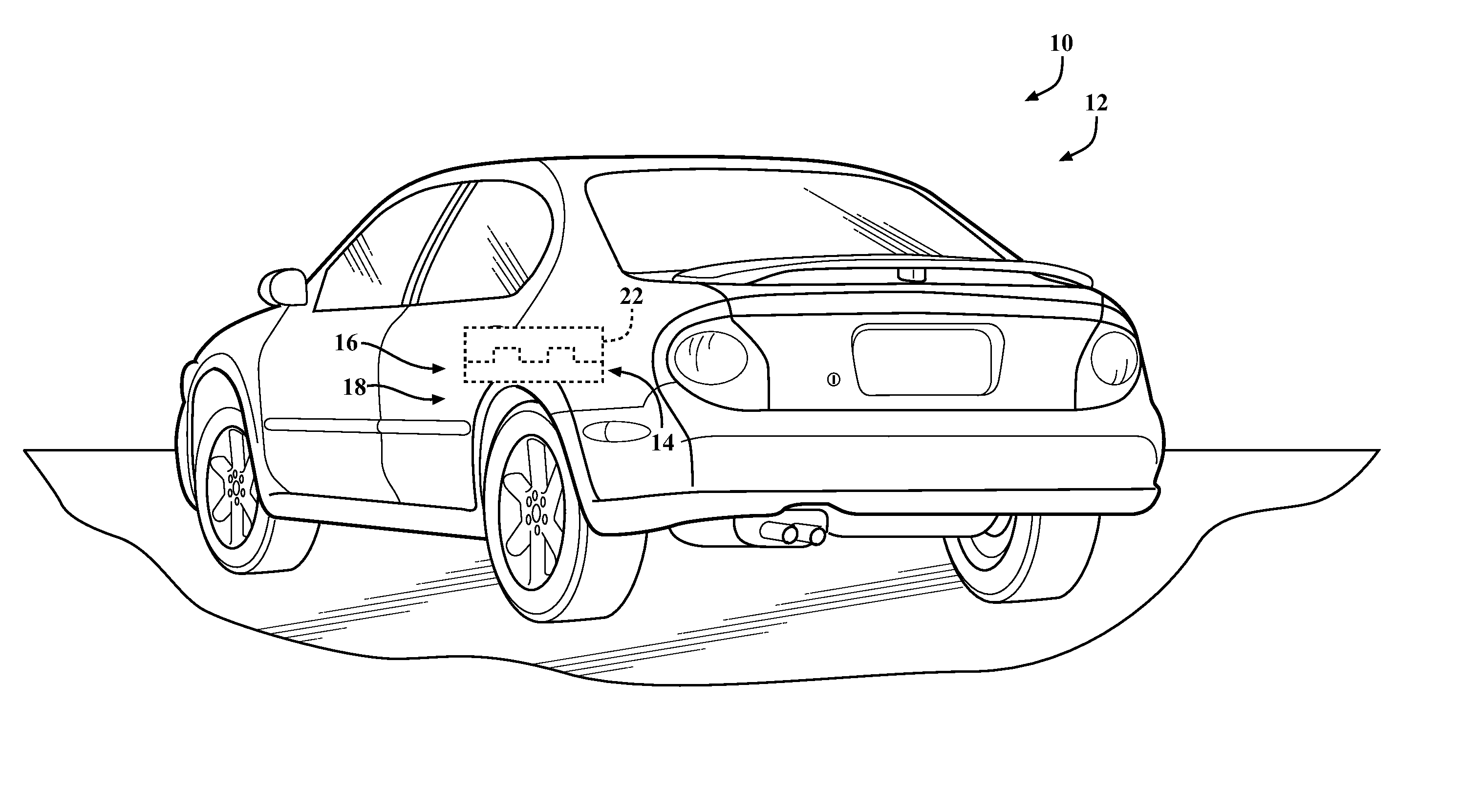
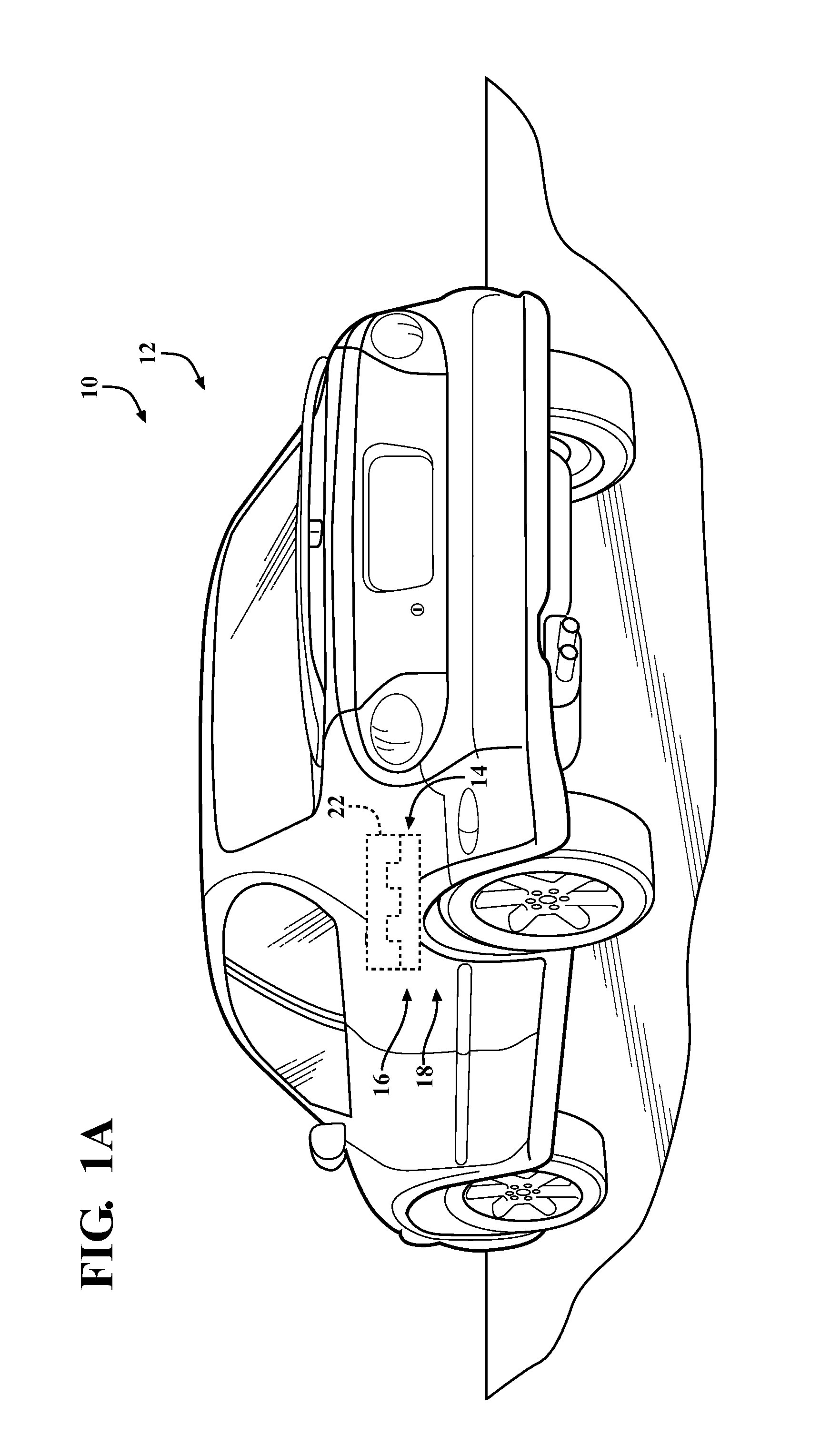
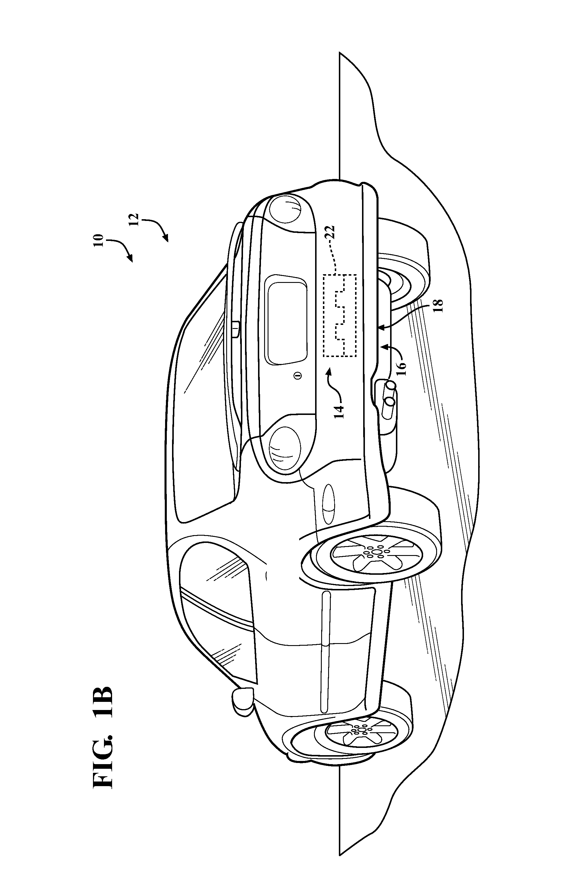
[0023]One aspect of the present invention provides for a vehicle component having a housing made of a non-metallic material and an antenna assembly. The antenna assembly includes a high-gain film-type antenna element, a low noise amplifier, and a feeding structure. Another aspect provides for a method for coupling an antenna assembly and a method for receiving a wireless signal.

[0024]FIG. 1A is a rear view of a vehicle 10 having an antenna assembly 12 disposed on an inner surfa...


PUM


Abstract

A vehicle component having a housing made of non-metallic material and having at least one surface made of metallic material is provided, and an antenna assembly is disposed in the vehicle component. The antenna assembly includes a high-gain film-type antenna element having an input for receiving a wireless signal, an output, and a ground portion is disposed on said non-metallic portion of the housing of said vehicle component. The antenna assembly also includes a low noise amplifier (LNA) and a feeding structure including a coaxial cable and a ground wire. The coaxial cable establishes electrical communication between the antenna element and the LNA, and the ground wire establishes an electrical connection between the ground portion of the antenna element and the metallic surface of the vehicle component.

Description

CROSS-REFERENCE TO PRIOR APPLICATION[0001]This U.S. Patent Application claims the benefit of U.S. Provisional Patent Application Ser. No. 61 / 749,624 filed Jan. 7, 2013, entitled “Antenna Assembly,” the entire disclosure of the application being considered part of the disclosure of this application and hereby incorporated by reference.BACKGROUND OF THE INVENTION[0002]1. Field of the Invention[0003]The present invention relates generally to antenna assemblies and, more specifically, to antenna assemblies for passenger vehicles.[0004]2. Related Art[0005]Antennas have traditionally been disposed on the exteriors of passenger vehicles and in the plain view of both the driver and others outside of the vehicle. Such antennas were traditionally rod-type antennas which extended outwardly from the front portion, the back portion or the roof of the vehicle. However, such a rod-type antenna may inhibit the driver's visibility and / or take away from the visual appeal or look of the vehicle, thus ...

Claims


Application Information

Patent Timeline
IPC IPC(8): H01Q1/32
CPCH01Q1/3233H01Q1/3283H01Q1/3291H01Q1/38H01Q23/00
Inventor MERRICK, MICHAELLI, QIANONUKI, TAKEHITOKOLLI, SOWJANYAIZI, ADHAM
Owner HARADA IND OF AMERICA
Why Eureka
Try Eureka