Dust detection apparatus having rapid clamping jig

A dust detection and fast technology, applied in the field of sensors, can solve the problems of troublesome removal, affecting the connection speed, and easy damage of metal probes, etc., and achieves the effects of convenient installation and disassembly, improved installation flexibility, and stable conversion data

Active Publication Date: 2014-03-26
深圳市辉翰科技发展有限公司
View PDF6 Cites 5 Cited by
  • Summary
  • Abstract
  • Description
  • Claims
  • Application Information

AI Technical Summary

Problems solved by technology

[0003] At present, the part of this type of probe used to sense dust is a rod-shaped metal probe. After the probe is installed, the metal probe extends into the clean gas pipe. The metal probe is washed by dust for a long time. After a period of use, the sensitivity of the metal probe is serious. Falling, the induction is not sensitive, the conversion data is unstable, and at the same time, the metal probe is washed and worn by dust, and the metal probe is easily damaged
[0004] Moreover, the existing metal rods (metal probes) are generally fixed on the connection part, and the connection part is directly welded on the probe box or the probe base, but it is very troublesome to take off by welding, and the metal rod is generally impossible If it is directly fixed on the equipment, it needs to install a fixing piece on the equipment to fix the metal rod. The fixing piece and the metal rod can be fixed by screw or adhesive. The screw connection is fixed because the probe box has been fixed with the metal rod. , and the probe box is connected with a signal line, so that when the screw is connected to the rotating probe, the signal line will interfere with the rotation of the probe and affect the connection speed
[0005] Moreover, when the connection part of the fixed connection is damaged, the entire probe needs to be replaced, but in fact the metal rod can still be used, which creates unnecessary waste and increases the cost of maintenance and replacement.

Method used


Image

  • Dust detection apparatus having rapid clamping jig
  • Dust detection apparatus having rapid clamping jig
  • Dust detection apparatus having rapid clamping jig

Examples


Embodiment Construction

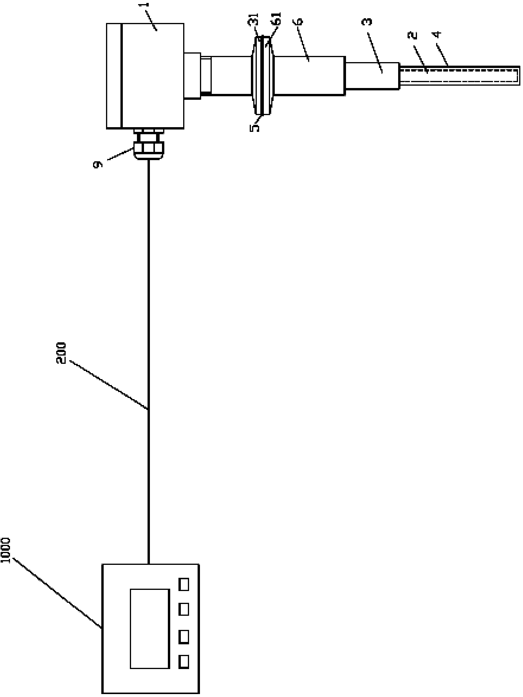
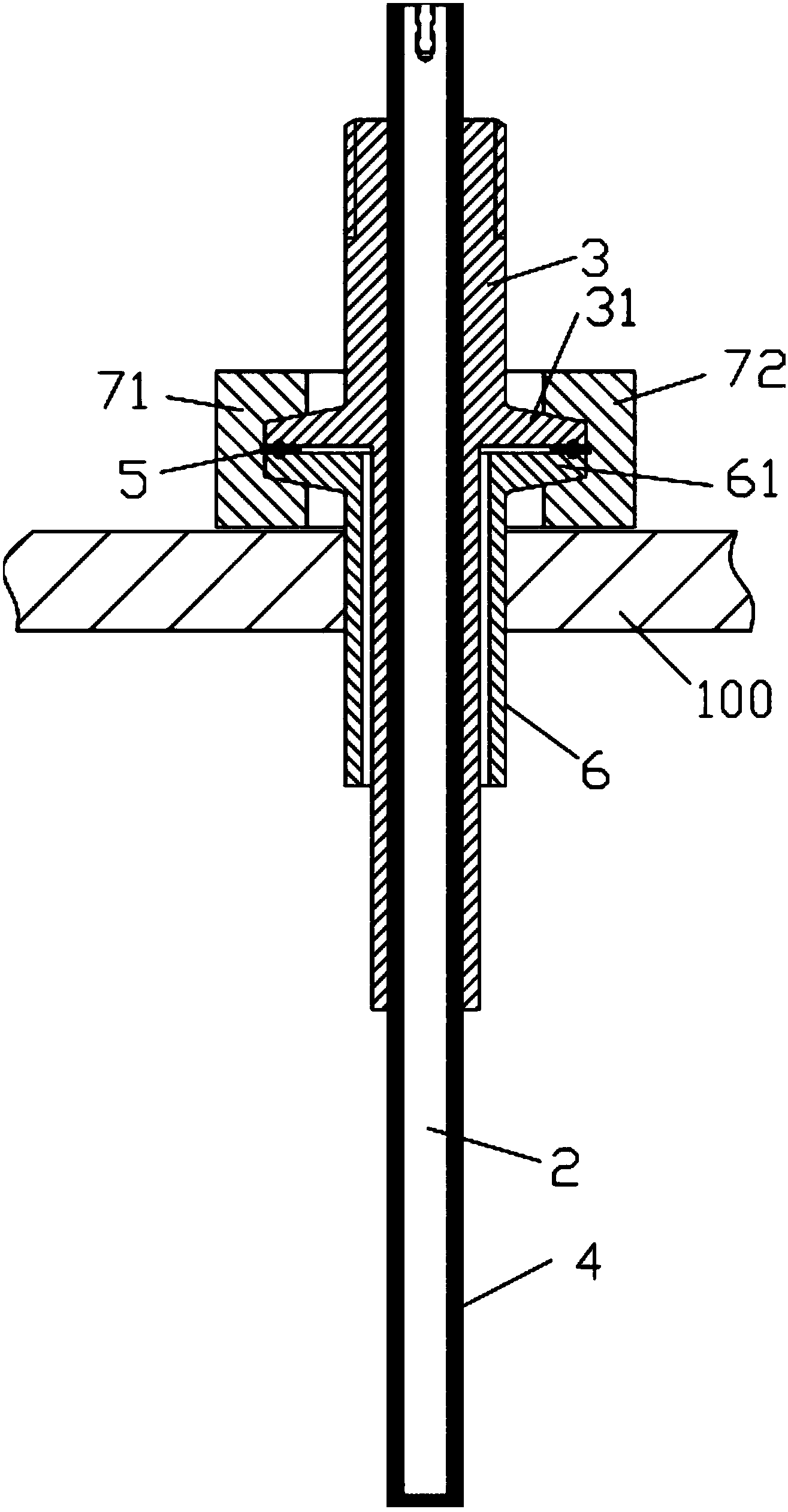
[0035] Examples, see e.g. Figures 1 to 10 As shown, a dust detection device with a quick clamping fixture includes a controller 1000, a signal line 200, a probe box 1 and a metal rod 2, the controller 1000 is connected to the metal rod 2 through the signal wire 200, and the metal rod 2 is fixed in the connecting sleeve 3 (it can be fixed by sticking or clamping), the lower end of the metal rod 2 protrudes from the lower end of the connecting sleeve 3, and the part of the metal rod 2 protrudes from the lower end of the connecting sleeve 3 For the sensing part, at least the surface of the sensing part is coated with a Teflon material layer 4, the upper end of the connecting sleeve 3 is screwed into the raised block at the bottom of the probe box 1, and the metal rod 2 protrudes from the upper end of the connecting sleeve 3 A part of it is inserted into the probe box 1;

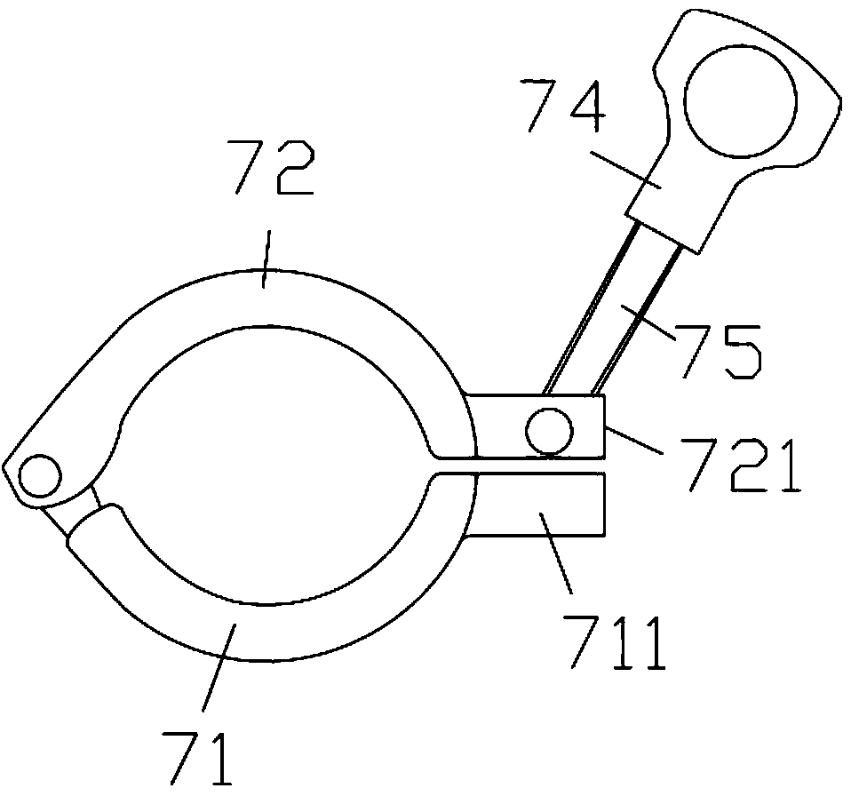
[0036] The outer wall of the middle part of the connecting sleeve 3 is formed with a radially extending upp...


PUM


Abstract

The invention discloses a dust detection apparatus having a rapid clamping jig. The apparatus comprises a controller, a signal line, a probe box and a metal rod, the metal rod is fixed in a connecting sleeve, the lower end of the metal rod extends out of the lower end of the connecting sleeve, the portion of the metal rod out of the lower end of the connecting sleeve is an induction portion, the surface of the at least the induction portion is coated with a Teflon coating layer, and the upper end of the connecting sleeve is screwed to the bottom of the probe box; and a radial-extending upper annular projection ring is molded on the outer wall of the central portion of the connecting sleeve, a radial-extending lower annular projection ring is molded on the top end surface of a lower connecting sleeve, an elastic ring is clamped between the upper annular projection ring and the lower annular projection ring, and the upper annular projection ring, the elastic ring and the lower annular projection ring are sleeved in the grooves on the inside wall of a left clamping block and a right clamping block of the jig. The lower connecting sleeve is fixed in a connecting hole of the apparatus, and probes can be rapidly connected through the jig, so the apparatus has the advantages of fast clamping speed, convenient installation and convenient dismounting.

Description

Technical field: [0001] The invention relates to the technical field of sensors, in particular to a dust detection device with a quick clamping fixture. Background technique: [0002] In the prior art, the raw blast furnace gas discharged from the top of the ironmaking blast furnace is separated from the large particle dust by the gravity dust collector, and then the fine powder is removed by the bag filter. At this time, the blast furnace gas is called clean gas. There is still a pressure of more than 120KPa and a temperature of more than 100°C, which is sent to the gas power generation device to utilize this part of energy to achieve the purpose of reducing consumption and saving energy. The coal gas residual pressure power generation device has high requirements for clean gas, and the dust content of the clean gas is required to be less than 10mg / m3. If the concentration is too high, the impeller of the gas residual pressure power generation device will be quickly washed ...

Claims


Application Information

Patent Timeline
Patent Type & Authority Applications(China)
IPC IPC(8): G01N27/60
Inventor 谢浔
Owner 深圳市辉翰科技发展有限公司
Why Eureka
Try Eureka