
Hollow fiber membrane

a hollow fiber membrane and fiber technology, applied in membrane technology, membranes, reverse osmosis, etc., can solve the problems of increasing pressure loss, reducing permeability, and enormous economic loss, and achieves the effect of minimizing filtration pressure loss, maximizing removal performance of contamination sources, and prolonging service life of hollow fiber membranes

Active Publication Date: 2020-03-24
LG CHEM LTD
View PDF38 Cites 0 Cited by
  • Summary
  • Abstract
  • Description
  • Claims
  • Application Information

AI Technical Summary

Benefits of technology

[0007]Therefore, an object of the present invention is to provide a hollow fiber membrane which increases the breaking strength and the tensile strength and simultaneously improves the permeability by allowing the porosity of the inside cross-section to be different depending on the depth.
[0008]Another object of the present invention is to provide a hollow fiber membrane which may decrease the filtration pressure loss.
[0018]According to an exemplary embodiment of the present invention, the service life of a hollow fiber membrane may be prolonged by minimizing the filtration pressure loss depending on the cross-sectional structure of the hollow fiber membrane, and the removal performance of a contamination source may be maximized or an optional separation performance may be improved while high permeability may be simultaneously expected.
[0019]Furthermore, a high porosity layer may be formed on the cross-section of the outermost part of the hollow fiber membrane to facilitate washing of the membrane, so that stability may be secured even during the long-term operation, and economic efficiency may be enhanced.

Problems solved by technology

In addition, efforts have been made to even remove fine contaminants by decreasing the porosity of the cross-section of the hollow fiber membrane in order to enhance the removal performance of the contaminants, but the filtration pressure loss is increased, so that the permeability rapidly decreases, and the economic loss was enormous in order to utilize this.
Various methods have been tried to overcome this, but it has been difficult to increase the water permeability by minimizing the filtration pressure loss, and simultaneously improve the removal rate and the strength.

Method used


Image

  • Hollow fiber membrane
  • Hollow fiber membrane
  • Hollow fiber membrane

Examples


Embodiment Construction

[0026]Reference will now be made in detail to the preferred embodiments of the present invention, examples of which are illustrated in the accompanying drawings. It will also be apparent to those skilled in the art that various modifications and variations can be made in the present invention without departing from the spirit or scope of the invention. Thus, it is intended that the present invention cover modifications and variations of this invention provided they come within the scope of the appended claims and their equivalents.

[0027]Description will now be given in detail of a drain device and a refrigerator having the same according to an embodiment, with reference to the accompanying drawings.

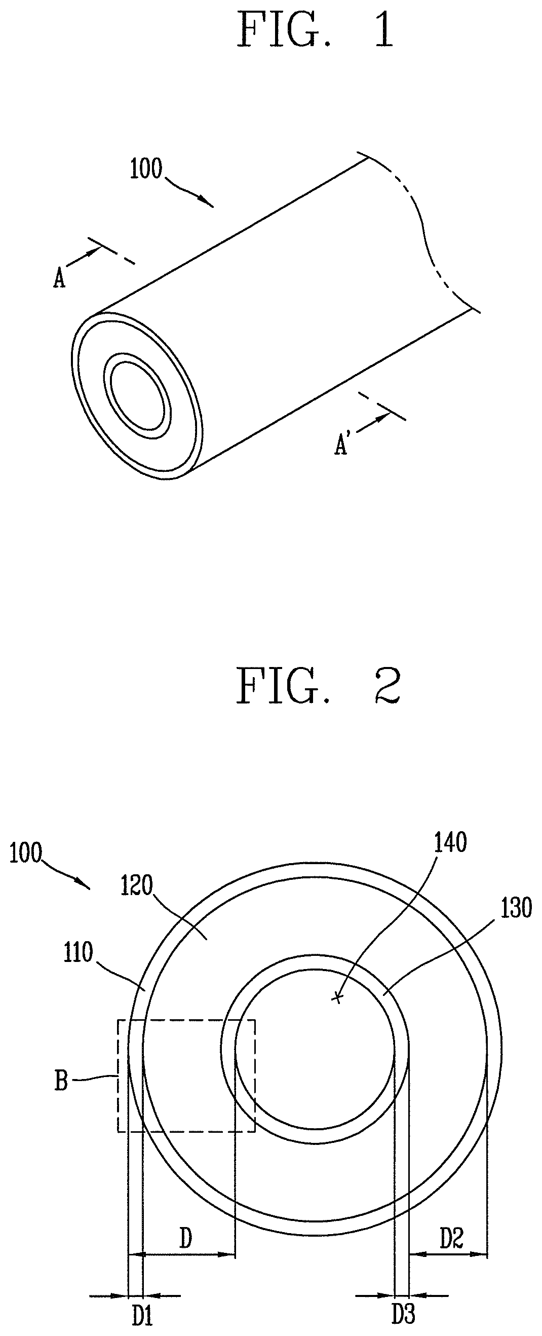
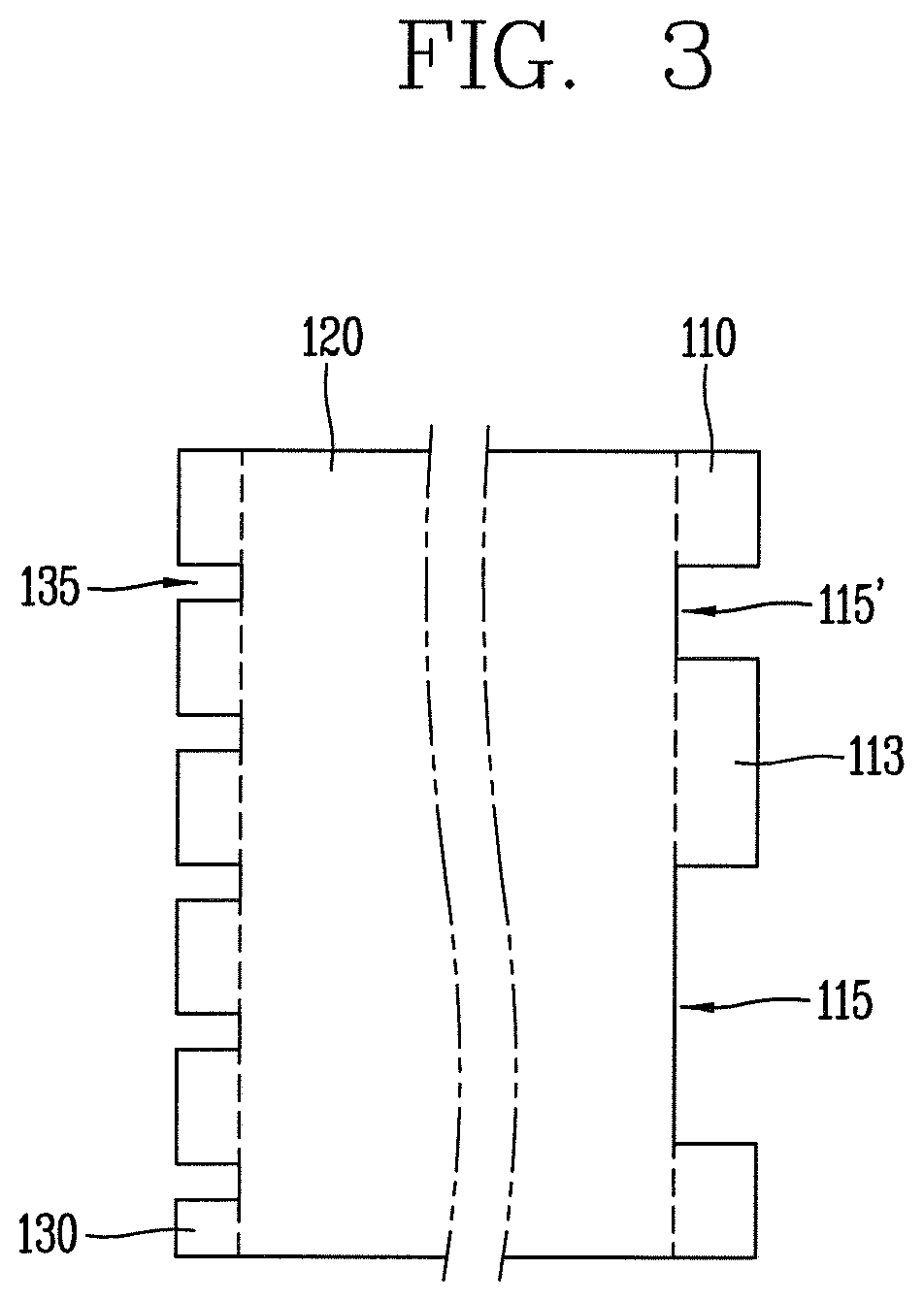
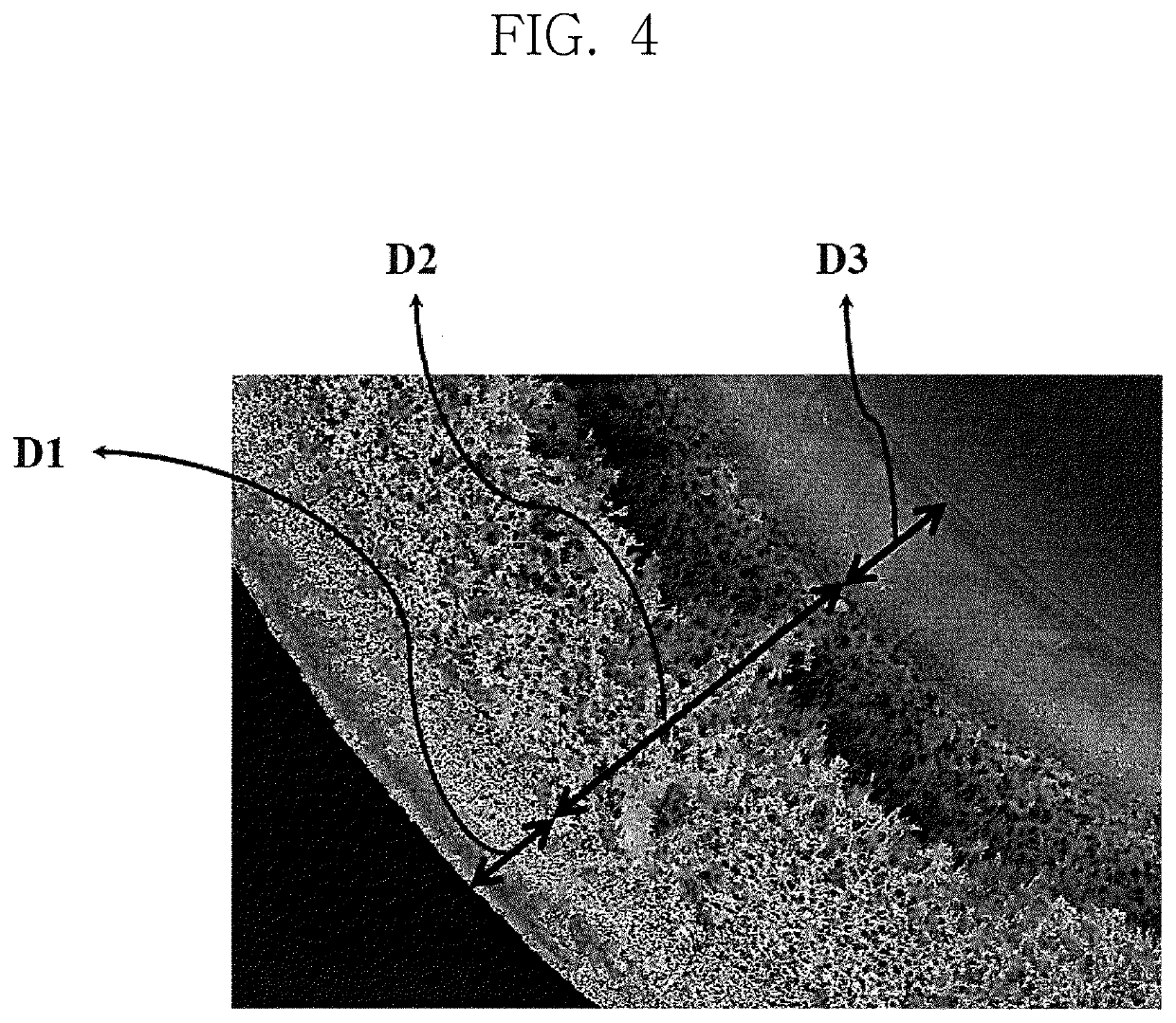
[0028]Hereinafter, a hollow fiber membrane according to an exemplary embodiment of the present invention will be described in more detail with reference to the drawings. In the present specification, like reference numbers are used to designate like constituents even though they are in di...


PUM

PropertyMeasurementUnit
porosityaaaaaaaaaa
porosityaaaaaaaaaa
porosityaaaaaaaaaa

Abstract

The present invention relates to a hollow fiber membrane. Provided is a cylindrical hollow fiber membrane having an inside in which a hollow part is formed along an axial direction, the hollow fiber membrane including: a first layer positioned at the outermost part so as to be exposed to the outside, and having pores formed therein to make raw water enter and leave via the pores; a second layer formed on the inside of the first layer to filter out contaminants from raw water as the raw water passes through; and a third layer to optionally separate or filter out contaminants from the raw water introduced through the second layer or introduced from the hollow part, wherein the first layer to the third layer are integrally formed; the porosity of the first layer is greater than the porosity of the third layer; and porosities are gradually decreased from the first layer to the third layer.

Description

[0001]CROSS-REFERENCE TO RELATED PATENT APPLICATIONS[0002]This application is a U.S. National Stage Application under 35 U.S.C. § 371 of PCT Application No. PCT / KR2014 / 006719, filed Jul. 23, 2014, which claims priority to Korean Patent Application No. 10-2013-0160586, filed Dec. 20, 2013, whose entire disclosures are hereby incorporated by reference.TECHNICAL FIELD[0003]The present invention relates to a hollow fiber membrane, and more particularly, to a hollow fiber membrane whose porosity is different depending on the depth of the cross-section.BACKGROUND ART[0004]In general, hollow fiber membranes are prepared by using a non-solvent phase separation method or a thermally induced phase separation method. Hollow fiber membranes produced by the aforementioned method are classified into a microfiltration membrane (MF), a ultrafiltration membrane (UF), a nanofiltration membrane (NF), and a reverse osmosis membrane (RO).[0005]A typical hollow fiber membrane has the outermost layer and ...

Claims


Application Information

Patent Timeline
Patent Type & Authority Patents(United States)
IPC IPC(8): B01D69/08B01D71/68B01D69/12B01D69/02B01D61/02B01D61/14
CPCB01D69/08B01D71/68B01D61/147B01D61/027B01D61/145B01D61/025B01D69/02B01D2325/04B01D2325/02B01D2325/24B01D2325/022B01D69/12B01D2325/0231B01D69/1214B01D69/1216
Inventor PARK, JOOYOUNGKIM, JONGDEOKLEE, JUNSEOK
Owner LG CHEM LTD
Learn More