Revascularisation localisation and pre and post quantitative coronary angiography

a quantitative coronary angiography and revascularisation technology, applied in the field of revascularisation localisation and pre and post quantitative coronary angiography, can solve the problems of time-consuming and laborious, and achieve the effect of better visual interpretation of any resultant imagery

Active Publication Date: 2020-03-31
KONINKLJIJKE PHILIPS NV
View PDF8 Cites 0 Cited by
  • Summary
  • Abstract
  • Description
  • Claims
  • Application Information

AI Technical Summary

Benefits of technology

[0033]By choosing the reference frame, from images acquired before treatment, a stenosis is more visible at this stage, providing for better visual interpretation of any resultant imagery.

Problems solved by technology

Therefore, obtaining QCA values takes time, can be tedious, and as such is sometimes omitted or only roughly estimated visually.

Method used


Image

  • Revascularisation localisation and pre and post quantitative coronary angiography
  • Revascularisation localisation and pre and post quantitative coronary angiography
  • Revascularisation localisation and pre and post quantitative coronary angiography

Examples


Embodiment Construction

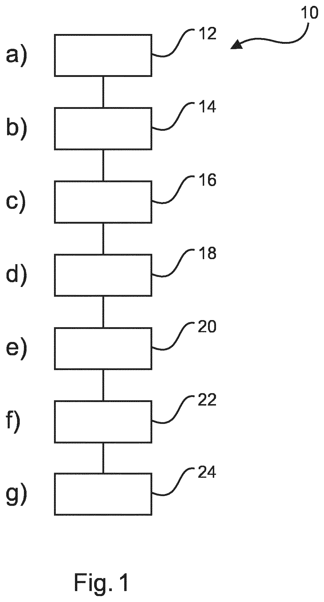
[0071]FIG. 1 shows a method 10 for automatic vascular treatment localization and quantification of a part of a vascular structure in its basic step. The method 10 comprises the following:

[0072]In a first providing step 12, also referred to as step a), at least one first image comprising a representation of a region of interest of a vascular structure is provided.

[0073]In a second providing step 14, also referred to as step b), at least one second image comprising a representation of the region of interest of the vascular structure is provided.

[0074]Between an acquisition of the at least one first image and an acquisition of the at least one second image, a vascular treatment might have been applied to the region of interest of the vascular structure. The representation of the region of interest of the vascular structure relates to spatial extension information of the vascular structure at least in one image plane.

[0075]In a first selecting step 16, also referred to as step c), at le...


PUM


Abstract

The present invention relates to localization of a vascular treatment and quantification of a part of a vascular structure. It is described to provide (12) at least one first image comprising a representation of a region of interest of a vascular structure. At least one second image comprising a representation of the region of interest of the vascular structure is provided (14). Between an acquisition of the at least one first image and an acquisition of the at least one second image, a vascular treatment might have been applied to the region of interest of the vascular structure, wherein the representation of the region of interest of the vascular structure relates to spatial extension information of the vascular structure at least in one image plane. At least one reference image from an image set formed from the at least one first image and the at least one second image is selected (16). At least one sample image from the image set formed from the at least one first image and the at least one second image is selected (18), wherein the at least one sample image is different to the at least one reference image. At least one image from the at least one sample image is registered (20) with the at least one reference image to provide at least one registered image. It is determined (22) if there exists at least one region of spatial discrepancy between the representation of the region of interest in the at least one reference image and the representation of the region of interest in the at least one registered image. Data is output (24) representative of the at least one region of spatial discrepancy.

Description

CROSS-REFERENCE TO PRIOR APPLICATIONS[0001]This application is the U.S. National Phase application under 35 U.S.C. § 371 of International Application No. PCT / EP2016 / 067755, filed on Jul. 26, 2016, which claims the benefit of European Patent Application No. 15306217.9, filed on Jul. 27, 2015. These applications are hereby incorporated by reference herein.FIELD OF THE INVENTION[0002]The present invention relates to an apparatus for localization of a vascular treatment and quantification of a part of a vascular structure, to a medical system for localization of a vascular treatment and quantification of a part of a vascular structure, and to a method for localization of a vascular treatment and quantification of a part of a vascular structure, as well as to a computer program element and a computer readable medium.BACKGROUND OF THE INVENTION[0003]In vascular treatments, for example in Percutaneous Transluminal Coronary Angioplasty (PTCA) to treat cardiac stenosis, information relating ...

Claims


Application Information

Patent Timeline
Patent Type & Authority Patents(United States)
IPC IPC(8): A61B6/00G06T7/62G06T7/00A61B6/03
CPCA61B6/504A61B6/5217A61B6/4441A61B6/487G06T7/62A61B6/469G06T7/0016A61B6/503A61B6/5235A61B6/032G06T2207/10116G06T2207/30101G16H50/30
Inventor FLORENT, RAOULAUVRAY, VINCENT MAURICE ANDRÉLELONG, PIERRE HENRI
Owner KONINKLJIJKE PHILIPS NV
Why Eureka
Try Eureka