Closed suction catheter

a closed, catheter technology, applied in the direction of suction devices, intravenous devices, other medical devices, etc., can solve the problem that the suction pressure cannot be maintained uniformly, and achieve the effect of ensuring the suction pressure and precise control of the suction force in the tub

Active Publication Date: 2020-04-07
JEONG & HWA
View PDF3 Cites 1 Cited by
  • Summary
  • Abstract
  • Description
  • Claims
  • Application Information

AI Technical Summary

Benefits of technology

[0010]As described above, in the closed suction catheter according to the present invention, it is possible to control the suction pressure of the tube in accordance with the degree of movement of the roller moving from the first end to the second end of the main body along the longitudinal groove of the main body. It is also possible to precisely control the suction force in the tube by controlling the movement of the roller relative to the length of the longitudinal groove. Further, a user can operate the roller with one hand and can check the suction pressure by viewing the position of the roller. In addition, since the tube passes through the main body and the end of the tube is directly connected to a suction machine, it is possible to maintain the suction force of the suction machine in the tube. Further, any one of the irregular portions of the roller is engaged with any one of the irregular portions of the main body such that the position of the roller is fixed, so it is possible to uniformly maintain the preset suction pressure.

Problems solved by technology

However, the push-type suction control valve cannot control the suction pressure, and the suction pressure gradually decreases during the course of the operation and thus the suction pressure cannot be maintained uniformly.

Method used


Image

  • Closed suction catheter
  • Closed suction catheter
  • Closed suction catheter

Examples


Embodiment Construction

[0014]Hereinafter, exemplary embodiments of the present invention will be described in detail with reference to the accompanying drawings.

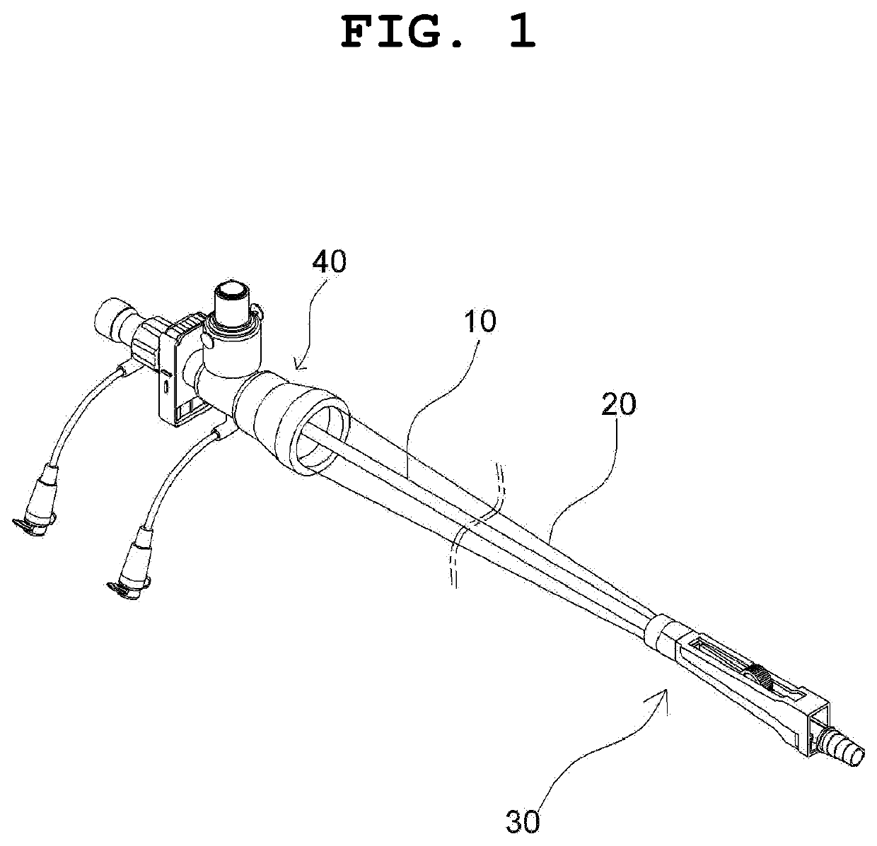
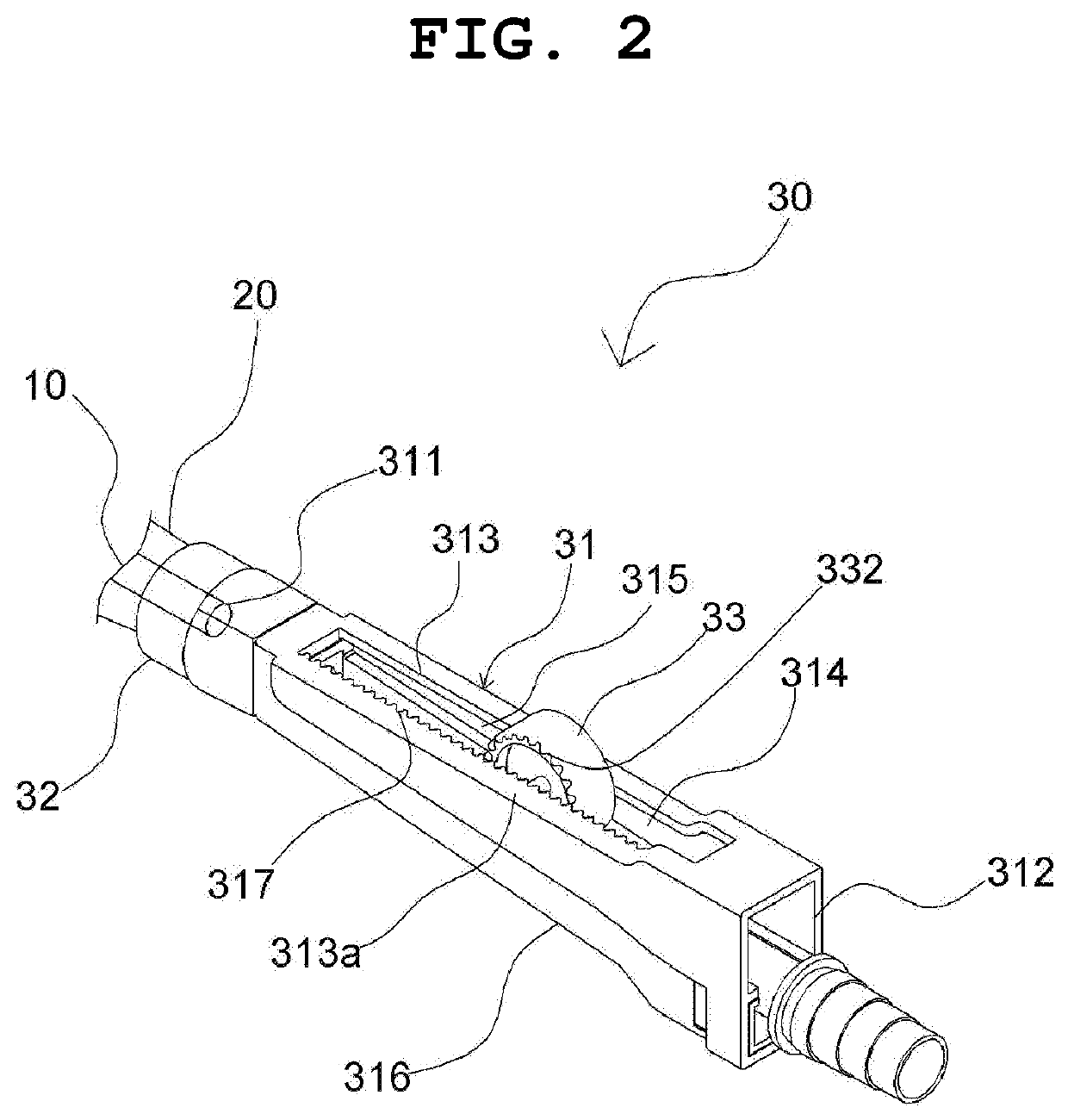
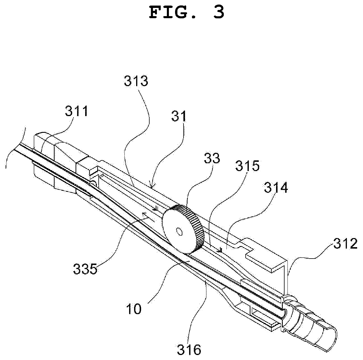
[0015]Referring to FIGS. 1 to 4, a closed suction catheter according to the present invention includes a tube 10 covered with a flexible shell 20, a suction controller 30 provided at a first end of the tube 10 and controlling a suction pressure, and a connection adaptor 40 provided at a second end of the tube 10.

[0016]In the closed suction catheter as described above, the suction controller 30 includes a main body 31 connected to the flexible outer skin 20 by a coupling ring 32, the main body 31 including: two tube holes 311 and 312 formed in the main body 31 such that the tube 10 passes through the main body 31; a longitudinal groove 313 formed at a position between the two tube holes 311 and 312, with a roller 33 installed in the longitudinal groove 313; a guide portion formed on a side wall 314 of the longitudinal groove 313 and guiding movemen...


PUM


Abstract

Disclosed is a closed suction catheter for removing respiratory secretions secreted from a patient's airway, the closed suction catheter including: a tube (10) covered with a flexible outer skin (20); a suction controller (30); and a connection adaptor (40), wherein the suction controller (30) includes a main body (31) being connected to the flexible outer skin (20) by a coupling ring (32) and including: two tube holes (311 and 312) formed in the main body (31); a longitudinal groove (313) formed between the tube holes (311 and 312), with a roller (33) installed in the groove (313); a guide portion (315) formed on a side wall (314) of the groove (313); and a bottom surface (316) inclindly formed at the main body (31) with the tube (10) placed on the bottom surface (316), such that an opening ratio of the tube (10) is controlled by movement of the roller (33).

Description

CROSS REFERENCE TO RELATED APPLICATION[0001]The present application is a continuation application of International Application No. PCT / KR2015 / 012816 filed on Nov. 27, 2015, which claims priority to Korean Application No. 20-2014-0009690 filed on Dec. 31, 2014, which applications are incorporated herein by reference.TECHNICAL FIELD[0002]The present invention relates generally to a closed suction catheter for removing respiratory secretions secreted from a patient's airway. More particularly, the present invention relates to a closed suction catheter, in which a roller mounted on a main body of a suction controller moves along a longitudinal groove, and thus the suction pressure of a tube is controlled in accordance with the degree of movement of the roller moving along the longitudinal groove.BACKGROUND ART[0003]Korean Patent No. 10-0799028 (registered on Jan. 22, 2008) discloses “Improved closed suction catheter assembly adaptor and system containing the same”.[0004]The closed sucti...

Claims


Application Information

Patent Timeline
Patent Type & Authority Patents(United States)
IPC IPC(8): A61M1/00A61M16/04
CPCA61M1/0086A61M1/0045A61M16/0463A61M2210/1025A61M2205/33A61M1/7415A61M1/86A61M1/741A61M1/7411A61M1/84
Inventor JEONG, IN HWA
Owner JEONG & HWA
Why Eureka
Try Eureka