
Hybrid wing rigging for wind-propelled vessel

a technology for rigging and wind-propelled vessels, which is applied in the field of rigging for wind-propelled vessels, can solve the problems of limiting the range of the vessel's point of sail, rigid wings, and inability to easily hoist or lower, so as to eliminate the effect of wind-induced heeling or thrust of the vessel, and easy hoisting or lowering

Active Publication Date: 2020-04-07
FAST FORWARD COMPOSITES CORP
View PDF2 Cites 1 Cited by
  • Summary
  • Abstract
  • Description
  • Claims
  • Application Information

AI Technical Summary

Benefits of technology

[0007]The present disclosure provides a hybrid wing for a wind-propelled vessel that addresses many practical challenges of conventional fixed, rigid wing sails. Particularly, the hybrid wing disclosed herein includes an airfoil-shaped mast and a sail movably coupled to a trailing edge of the airfoil-shaped mast. The sail can be readily hoisted or lowered along the airfoil-shaped mast. In addition, a swiveling masthead coupled to a top section of the airfoil-shaped mast enables a system of stays to extend from the masthead to the vessel body such that the stays are positioned outside of a rotational range of the airfoil-shaped mast. The result is that the system of stays does not restrict the rotation of the airfoil-shaped mast, allowing the airfoil-shaped mast to align to any wind direction when the sail is lowered, e.g., when anchored or docked, which eliminates wind-induced heeling or thrust of the vessel typical of fixed, rigid wing sails.
[0012]The swiveling masthead may include a center portion and a plurality of arms extending outwardly from the center portion, and the first end of each of the plurality of stays is connected to one of the plurality of arms. The swiveling masthead may be positioned substantially above the airfoil-shaped mast and may be configured to rotate independent of the airfoil-shaped mast. The swiveling masthead may also be configured to rotate about a longitudinal axis of the airfoil-shaped mast. Furthermore, the swiveling masthead may be equipped with one or more axial bearings to facilitate rotation of the swiveling masthead about the longitudinal axis of the airfoil-shaped mast, and may be equipped with one or more thrust bearings to sustain a downward load effected by a wind force exerted on the rigging.

Problems solved by technology

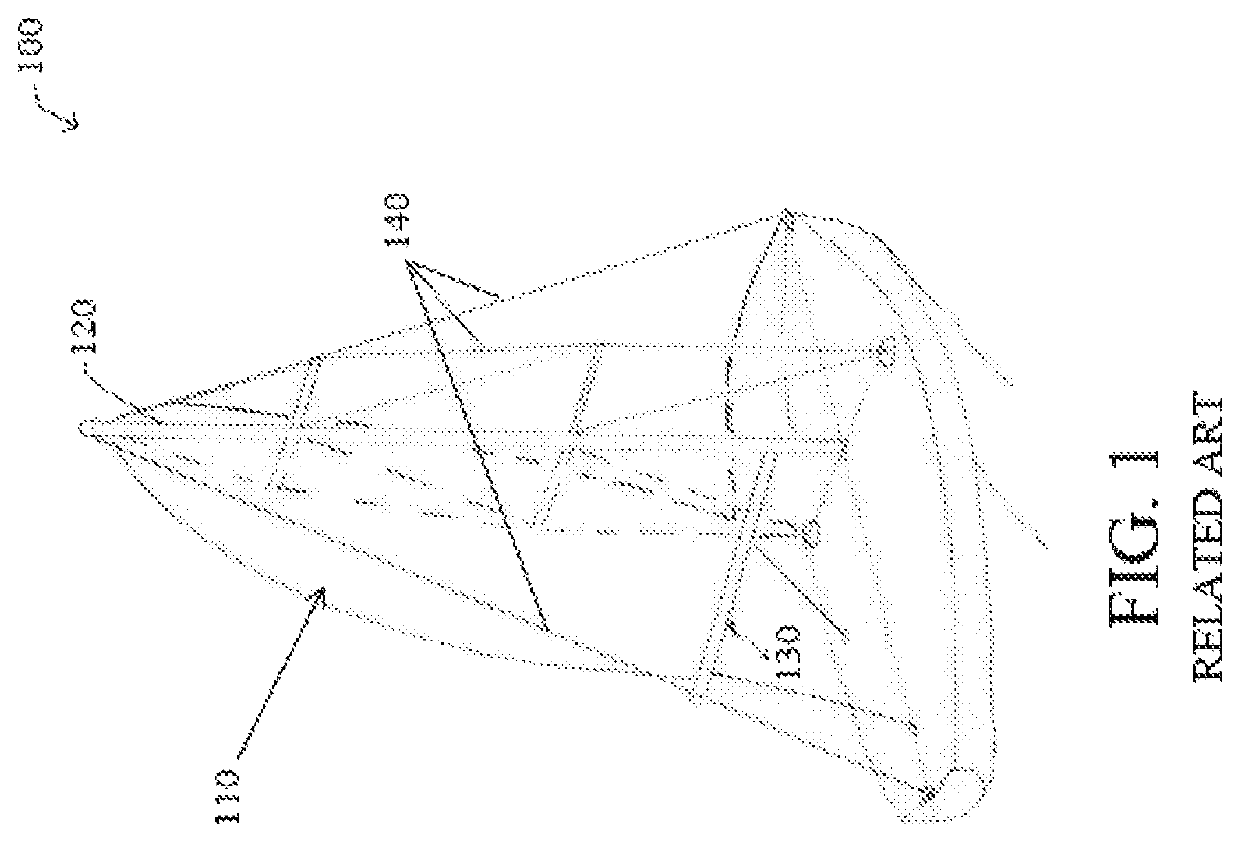
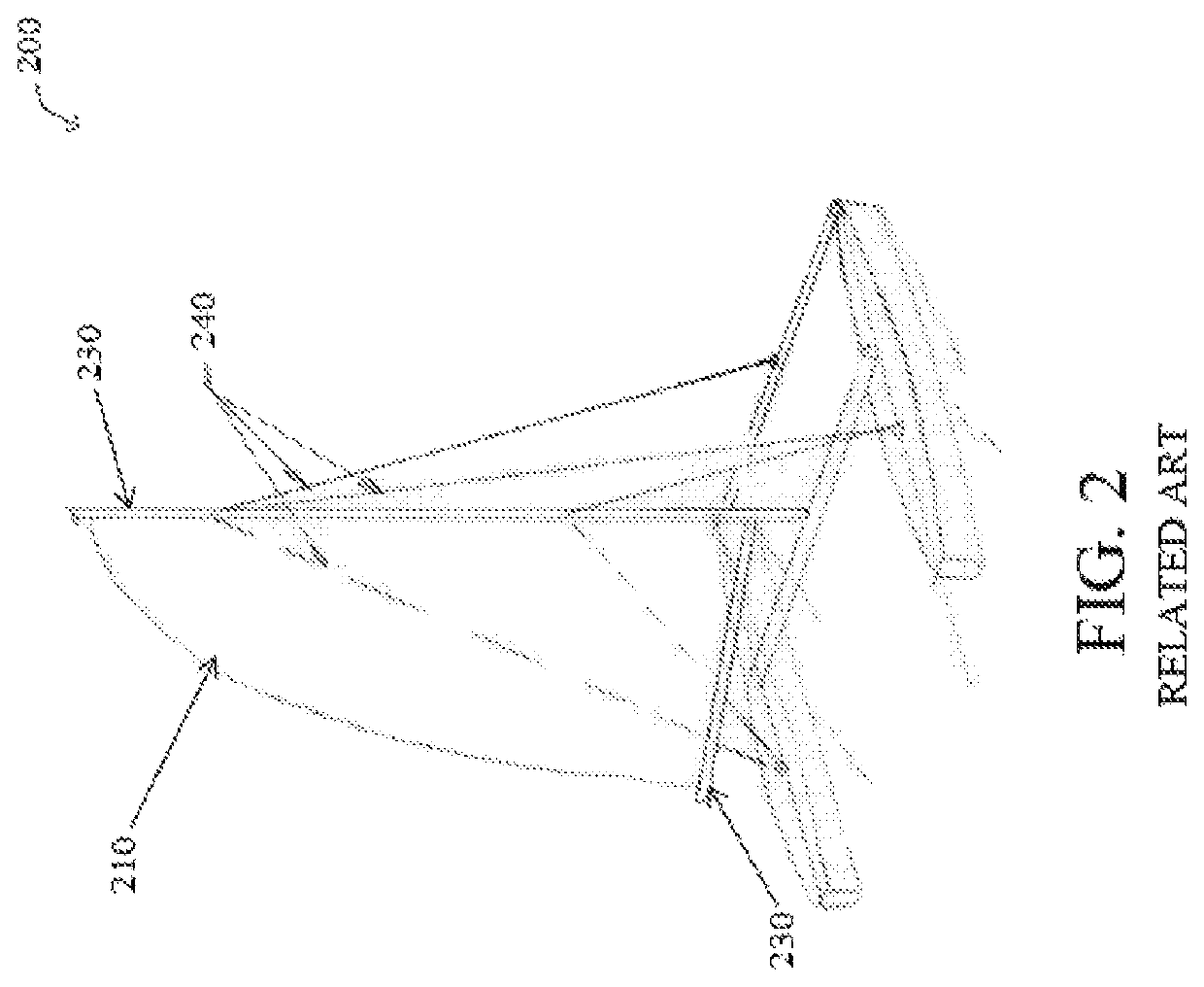
The drawback with this system, however, is that the aft-ward direction of the stays 240 limits the angle of boom 230, which in turn limits the vessel's point of sail range.
But rigid wings, except at such advanced levels of sailing as the America's Cup, are very impractical in every day sailing.
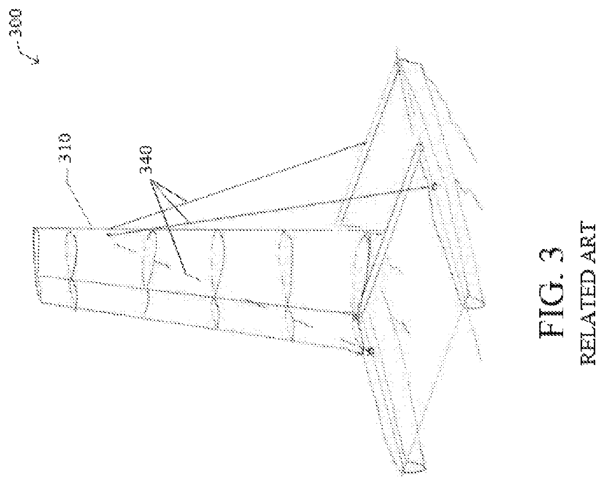
Additionally, the conventional wing sail 310 cannot be reefed (i.e., made smaller) when the wind increases, it cannot be easily hoisted or lowered, except with a dock or barge-mounted crane, and it cannot be left up at moorings or when docked as changes in wind strength and direction can exert high sailing loads on the vessel 300, putting strain on the vessel and potentially causing the vessel to capsize.

Method used


Image

  • Hybrid wing rigging for wind-propelled vessel
  • Hybrid wing rigging for wind-propelled vessel
  • Hybrid wing rigging for wind-propelled vessel

Examples


Embodiment Construction

[0027]Hereinafter, embodiments of the present disclosure will be described in detail with reference to the accompanying drawings. As those skilled in the art would realize, the described embodiments may be modified in various different ways, all without departing from the spirit or scope of the present disclosure. Further, throughout the specification, like reference numerals refer to like elements.

[0028]The terminology used herein is for the purpose of describing particular embodiments only and is not intended to be limiting of the disclosure. As used herein, the singular forms “a,”“an,” and “the” are intended to include the plural forms as well, unless the context clearly indicates otherwise. It will be further understood that the terms “comprises” and / or “comprising,” when used in this specification, specify the presence of stated features, integers, steps, operations, elements, and / or components, but do not preclude the presence or addition of one or more other features, integer...


PUM


Abstract

A rigging for a wind-propelled vessel includes: a rotating airfoil-shaped mast; a sail movably coupled to a trailing edge of the airfoil-shaped mast and configured to be hoisted or lowered along the airfoil-shaped mast; a swiveling masthead coupled to a top section of the airfoil-shaped mast; and a plurality of stays supporting the airfoil-shaped mast, each stay having a first end connected to the swiveling masthead and a second end connected to a hull of the vessel.

Description

CROSS-REFERENCE TO RELATED APPLICATION[0001]This application claims the benefit of priority to U.S. Provisional Patent Application No. 62 / 449,188, filed in the United States Patent and Trademark Office on Jan. 23, 2017, the entire contents of which are incorporated herein by reference.TECHNICAL FIELD[0002]The present disclosure relates generally to sailing vessels, and more particularly, to a rigging for a wind-propelled vessel.BACKGROUND[0003]Wind-propelled vessels, such as sail boats, yachts, catamarans, and the like, are generally driven either partly or entirely by sails. For example, FIG. 1 illustrates a conventional mono-hull vessel 100 including a curved, triangular fabric sail 110, which at different points thereof takes a different angle to the vessel 100. The sail 110 is able to convert wind energy into motion of the vessel 100 by redirecting the power of the wind to propel the vessel 100 along water. The sail 110 is typically held up by a mast 120 extending vertically fro...

Claims


Application Information

Patent Timeline
Patent Type & Authority Patents(United States)
IPC IPC(8): B63H9/06B63H9/10B63H9/08B63B15/00B63B15/02
CPCB63H9/061B63H9/10B63H9/08B63B2015/005B63B15/0083B63H9/0621B63B15/02B63H2009/086
Inventor ZENOZ, TOMAS FERNANDO GONZALEZ
Owner FAST FORWARD COMPOSITES CORP
Learn More