
Adjustable index mount for firearms

a technology for index mounts and firearms, applied in the field of adjustable index mounts, can solve the problems of increasing the likelihood of snagging components on clothing or other objects, affecting the use of firearms, so as to reduce the lateral profile of the paddle on the firearm, the effect of convenient us

Active Publication Date: 2020-04-07
LEAPERS
View PDF7 Cites 5 Cited by
  • Summary
  • Abstract
  • Description
  • Claims
  • Application Information

AI Technical Summary

Benefits of technology

The present invention is about an adjustable index mount that can be easily installed and adjusted to fit a user's preferences and grip. It allows a user to quickly and efficiently install the mount and then adjust it to precisely fit their particular needs and provides improved recoil management and rapid fire stability due to the consistent placement of a user's digits and / or hand on the firearm. The selectively configurable mount can have a forward cant, a neutral cant and / or a rearward cant to allow a user to precisely customize the index mount to their particular grip. The inward projection of the paddle also reduces the lateral profile of the index mount to provide enhanced maneuverability.

Problems solved by technology

While these components are helpful in gripping and controlling the firearm, they can be tedious to set up and properly configure for users of different stature.
A component might work for one user's body type or user's grip style, however, that same component may be completely incompatible with another user's body type or grip.
Further, these components can vary in size, with some being rather large and projecting too far away from the firearm, thereby increasing the likelihood of snagging that component on clothing or other objects.
In addition, because these components are stationary, a user may have to experiment and reposition the components in different areas of the firearm, requiring disassembly and removal from the firearm.

Method used


Image

  • Adjustable index mount for firearms
  • Adjustable index mount for firearms
  • Adjustable index mount for firearms

Examples


Embodiment Construction

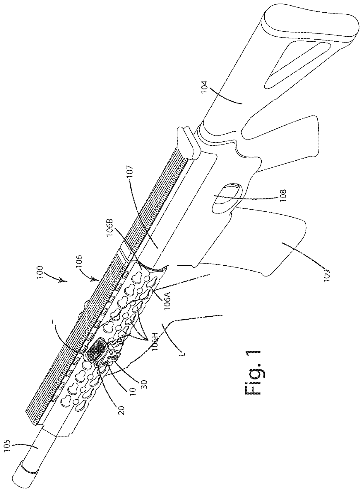
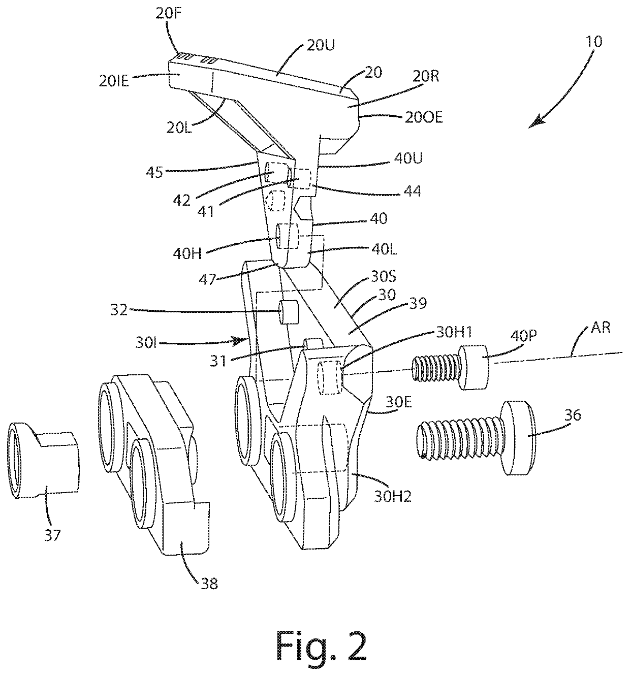
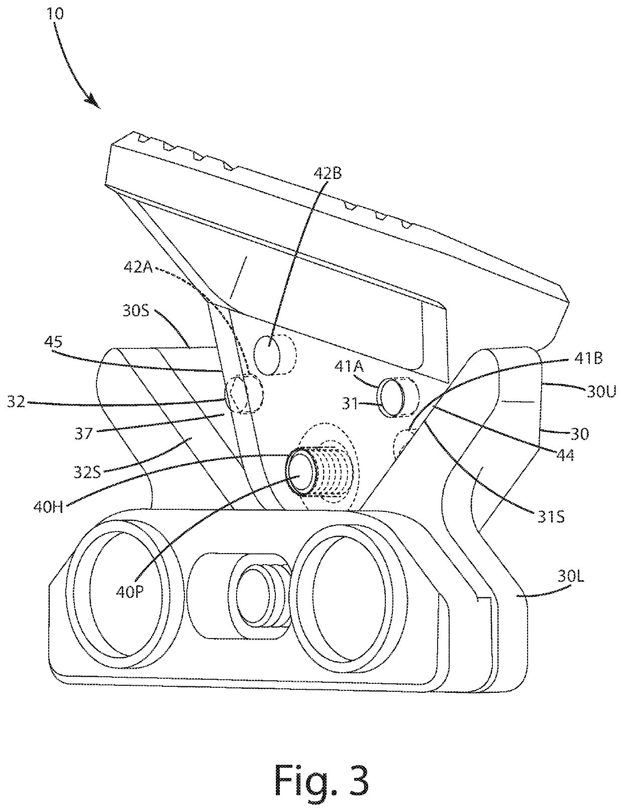
[0027]A current embodiment of an adjustable index mount 10 for a firearm is illustrated in FIGS. 1-9 and generally designated 10. The index mount is configured to be mounted to a firearm, for example a handguard of a firearm 100. The firearm 100 illustrated is in the form of an AR-15, but of course can be any other type of firearm. The firearm 100 can include a stock 104 configured to shoulder against a user, a barrel 105, a handguard 106, an upper receiver 107 and a lower receiver 108, which is configured to receive a removable magazine 109. The firearm can be split into left and right halves by a bisecting plane BP. The index mount can be mounted to the handguard as shown, but with other firearms or weapons, can be mounted to other parts of those items, such as a frame, a stock, a slide, upper or lower receivers or the like. The index mount 10 also is shown as being configured to mount to holes 106H defined by the handguard, or alternatively, directly to a picatinny rail or other ...


PUM


Abstract

An index mount for a firearm includes a mounting base, a connector flange and a selectively configurable paddle, joined with the connector flange, and configured to establish a resting surface to index a digit of a user relative to the firearm and consistently establish a particular grip relative to the firearm. The mount can include an indexing element that aligns and / or sets the paddle in first or second positions relative to the mounting base. The paddle can be configured with a forward cant and / or a rearward cant and can be adjusted to fit the user's preferences. The paddle can include an upper surface canted at an outward angle between 55° and 85°, inclusive. A related method of use is provided.

Description

BACKGROUND OF THE INVENTION[0001]The present invention relates to firearms, and more particularly to an adjustable index mount that assists a user in establishing a consistent and comfortable grip on a firearm.[0002]There is a variety of accessories available to consumers to customize their firearms, particularly modern sporting rifles, such as the AR15. Some of these accessories include pistol grips, angled fore grips, hand stops and barricade rests. These components can be attached to a firearm, such as a rifle, like the AR15. When attached to a rifle, these components typically are joined with the front handguard covering the barrel of the firearm. When in place, these components can assist a user in operating the firearm in a consistent manner. Most of these components are rigid, immovable projections against which a user can index a hand or digits to establish a solid, consistent grip on the firearm. Thus, when using the firearm, the user can attain a proper and consistent shoo...

Claims


Application Information

Patent Timeline
IPC IPC(8): F41A35/06F41C23/16F41C27/00
CPCF41A35/06F41C27/00F41C23/16F41C23/14
Inventor DING, TAI-LAIYU, TAT SHING
Owner LEAPERS
Learn More