
Method and microscope for measuring and calculating heights on curved surface of microscope slide

a technology of curved surface and microscope, which is applied in the field of method and microscope for measuring and calculating heights on curved surface of microscope slide, can solve the problems of blurry image, affecting observation results and quality of images photographed by microscope, and difficulty in seeing changes in height, etc., and achieves high imaging definition, accurate measurement, and fast micro image scanning of sample objects

Active Publication Date: 2020-04-07
YIN YUEFENG
View PDF14 Cites 0 Cited by
  • Summary
  • Abstract
  • Description
  • Claims
  • Application Information

AI Technical Summary

Benefits of technology

[0060]The present invention has beneficial effects that the heights on the curved surface of any one of the microscope slides can be accurately measured, and the method for measuring and calculating the heights on the curved surface can be applied to automatic scanning microscopes to realize the fast micro image scanning of sample objects on the microscope slides. Particularly under high-power lens, advantages of high imaging definition, high scanning speed, high efficiency and automation of the present invention are more outstanding.

Problems solved by technology

Surfaces of precise components manufactured with modern advanced technologies are already very “flat”, and it is hence difficult to see changes of “heights” on the curved surfaces of these precise components with human eyes.
However, in some scientific fields requiring extreme precision, for example, in a microscopic world magnified by an optical microscope, subtle changes can be magnified many times, thereby greatly affecting observation results and quality of images photographed by the microscope.
However, at high magnification (for example, above 100 times), since the DOF is small, a subtle height change (in micron dimension) of the curved surface of the microscope slide may cause that the distance between the sample on the microscope slide and the microscope lens exceeds the DOF, the image observed is hence blurry, and the image photographed is also blurry.
As described above, the change of height on the curved surface of the microscope slide may greatly affect the quality of image at high magnification.
However, at high magnification, for example above 100 times, since the DOF is small, a micrometer-scale change of height on the curved surface of the microscope slide may cause the samples exceeding the DOF.
Therefore, the efficiency at high magnification is very low, which hence brings great obstacles to scientific research and technology development because there are many samples placed on one microscope slide and the distance needs to he readjusted during each observation of the samples.
However, the influence of the height change of the curved surface of the microscope slide on the image shot by the microscope is still not overcome.
However actually, it is a method with a large error when applied to a high-power microscope with magnification greater than 100 times and is unable to achieve auto-focused fast photographing and scanning.

Method used


Image

  • Method and microscope for measuring and calculating heights on curved surface of microscope slide
  • Method and microscope for measuring and calculating heights on curved surface of microscope slide
  • Method and microscope for measuring and calculating heights on curved surface of microscope slide

Examples


embodiment 1

[0069]

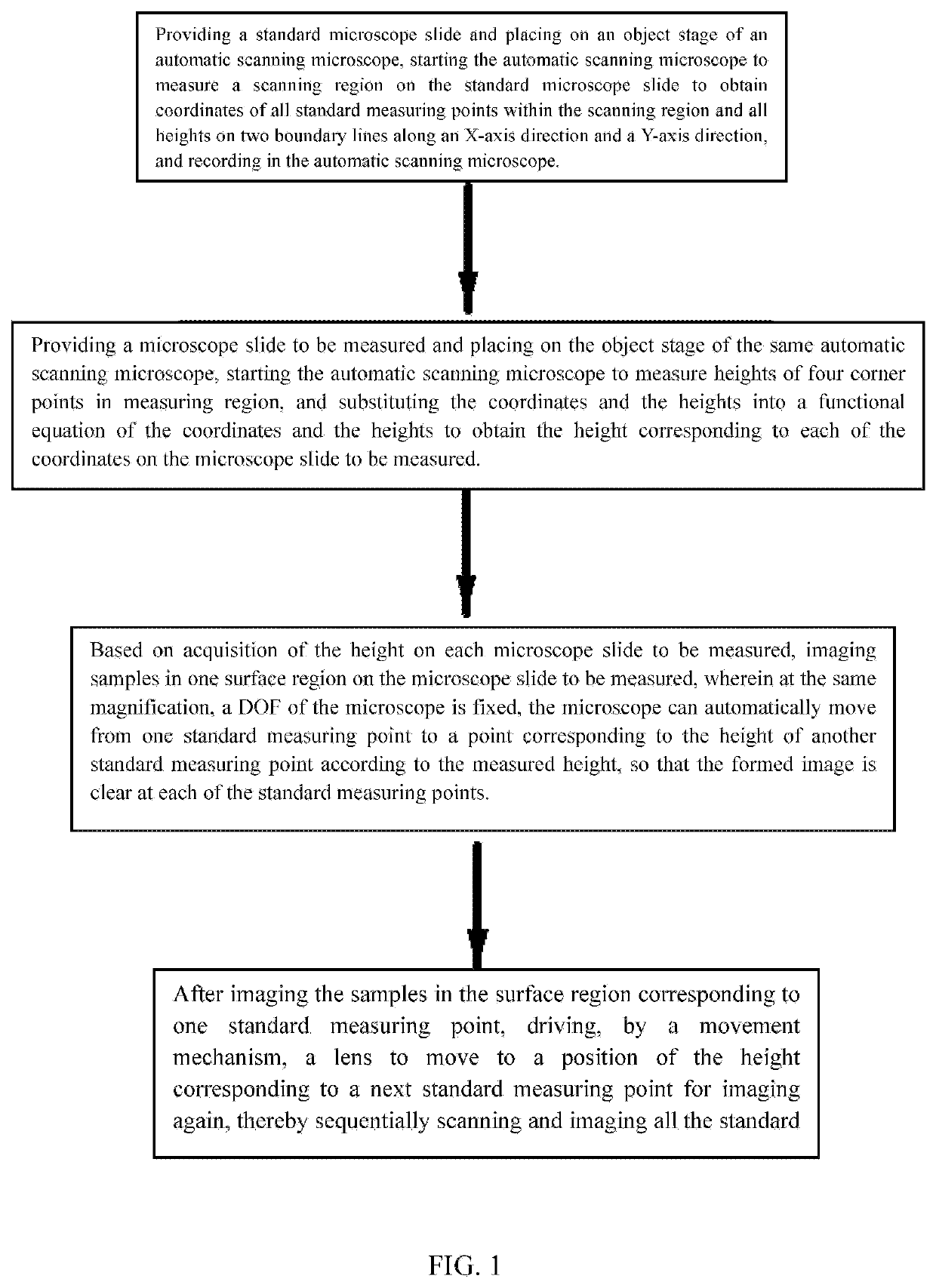
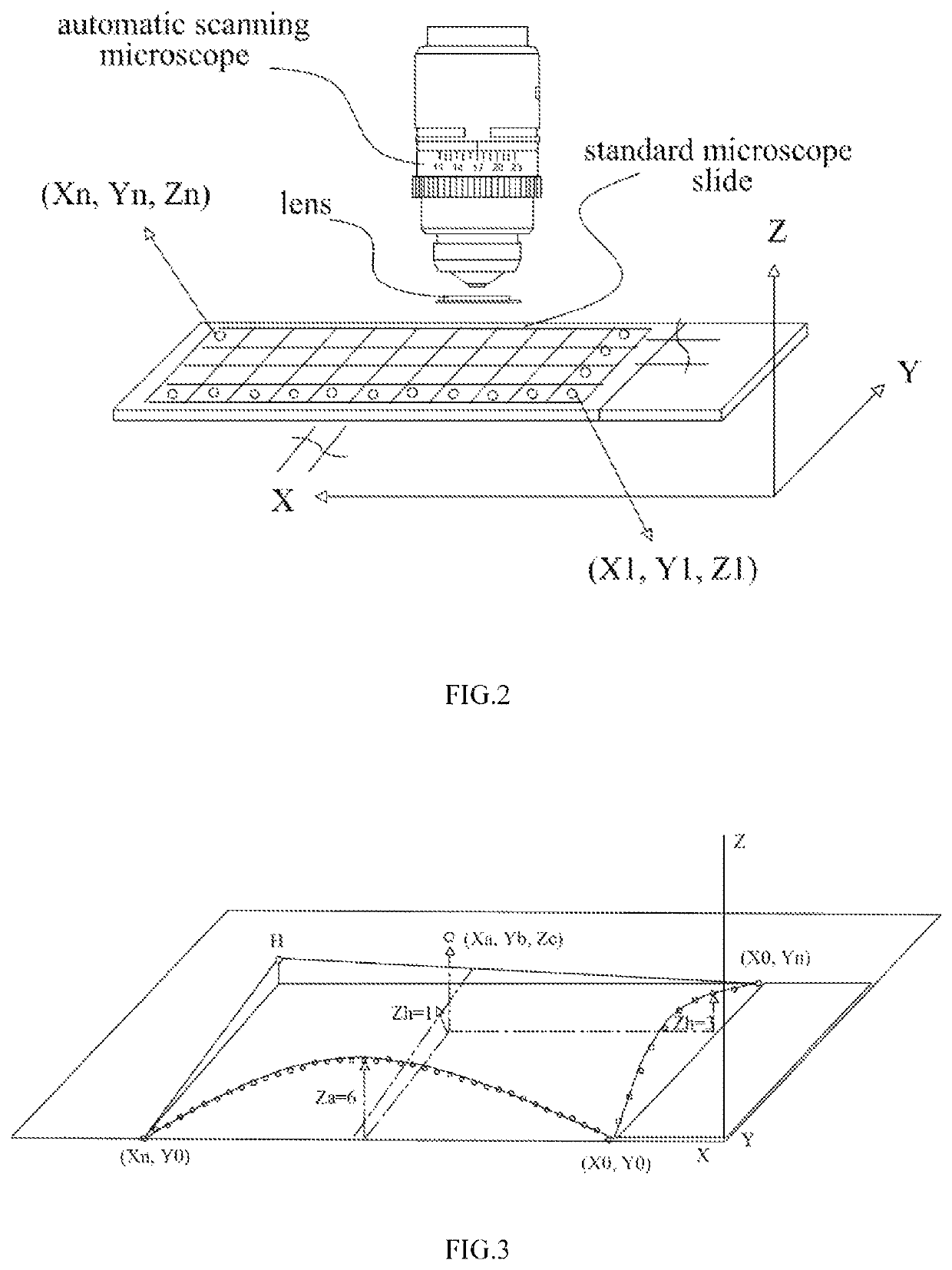
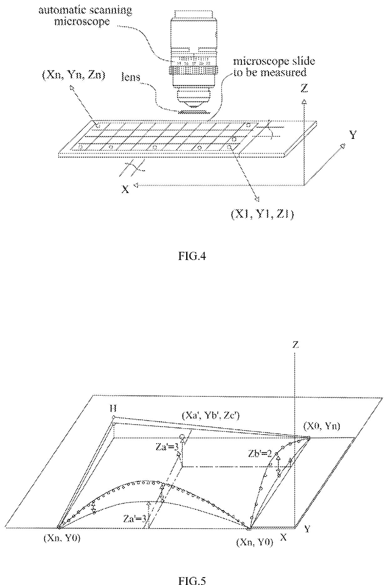
[0070]Scanning of standard microscope slides: preparing a plurality of standard microscope slides; taking a plurality of blank microscope slides; uniformly coating a single layer of the sample on the microscope slides; accurately placing the microscope slides on a sample rack of a scanning instrument; setting a software to define a scanning region of 2.5 cm×1.5 cm in length and width; sampling scanning the region with 27 visual fields scanned at equal intervals in an X-axis direction, 13 visual fields scanned at equal intervals in a Y-axis direction and 351 visual fields sampled in the overall region; and after dropping oil onto the sample, using an NA1.25 100× lens of olympus company to focus a first line x(i, 0) (a value of i is 0-26) so as to obtain 27 focused heights ZB(i, 0) on an x axis:[0071]0.5, 0.684568671, 0.913734812, 0.960046768, 1.024200047, 0.785085559, 0.871537623, 0.873252109, 0.464664036, 0.591254547, 0.601890489, 0.313716038, 0.444767363, 0.040638322, 0.05573...

embodiment 2

[0105] a microscopic scanning method of the microscope:

[0106]Scanning patterns of the samples on the microscope slides by applying the heights on the curved surfaces of the microscope slides obtained in the embodiment 1.

[0107]A single layer of samples (which are microspheres uniform in size in the present embodiment) are uniformly coated on the microscope slides. The software is set to define the scanning region of 2.5 cm×1.5 cm in length and width. The region is sampling scanned by the microscope with 27 visual fields scanned at equal intervals in the X-axis direction, 13 visual fields scanned at equal intervals in the Y-axis direction, and 351 visual fields sampled in the overall region. The microspheres are uniformly distributed in the 351 visual fields.

[0108]The heights of the focused points within the 351 visual fields are obtained by the method of the embodiment 1. Under the NA1.25 100× lens, the DOF of the microscope lens is fixed. Therefore, it only needs to adjust a distanc...


PUM


Abstract

A method for measuring and calculating the height of a microscope slide and estimating the position of the microscope slide in a microscope system based on the height is provided so as to obtain a clear image under continuous scanning at high magnification. In the present invention, a standard microscope slide is used as a template to obtain heights of all standard measurement points on another microscope slide to be measured. The method is realized through a conversion relationship of a functional equation set of coordinates and the heights.

Description

FIELD OF THE INVENTION[0001]The present invention relates to a method for measuring and calculating heights of points on a curved surface of a curved object through measuring coordinates and heights of a plurality of points on another curved surface object with a standard size and material which are the same as those of the curved surface object to be measured and calculated, and particularly relates to a method for measuring and calculating heights on a curved surface of a microscope slide, which is applied to microscopic scanning for fast imaging.BACKGROUND OF THE INVENTION[0002]The outer surface of any object can be regarded as a regular or irregular curved surface. Surfaces of precise components manufactured with modern advanced technologies are already very “flat”, and it is hence difficult to see changes of “heights” on the curved surfaces of these precise components with human eyes. However, in some scientific fields requiring extreme precision, for example, in a microscopic ...

Claims


Application Information

Patent Timeline
Patent Type & Authority Patents(United States)
IPC IPC(8): G02B21/00G01B11/06G02B21/36G01B21/04
CPCG01B11/0608G02B21/002G01B21/042G02B21/367
Inventor YIN, YUEFENG
Owner YIN YUEFENG
Learn More